
USER MANUAL Manual

Configuring Your Block I/O
Chapter 3
3-6
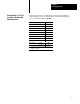
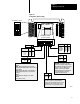
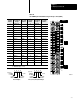
Figure 3.3
I/O
Image T
able for One Assigned Rack Number
017
Output Image
Input Image
0
1
2
3
4
5
6
7
710
017
0
1
2
3
4
5
6
7
710
1791IOVW1791IOBW
Rack 1
4 1791IOBW or 1791IOVW per rack
1st 1/4 rack = module group 01
2nd 1/4 rack = module group 23
3rd 1/4 rack = module group 45
4th 1/4 rack = module group 67
Block 1 Inputs
Block 2 Inputs
Block 1 Outputs
1
2
10933I
1791IOVW1791IOBW
Block 3 Inputs
Block 4 Inputs
Block 2 Outputs
Block 3 Outputs
Block 4 Outputs
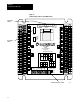
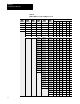
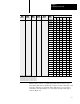
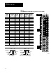
Figure 3.4
Input
T
able Usage Example for One Starting I/O Group with 1791IOBW
and IOVW
11107654321
110
111
Starting
I/O Group
0
0
Input Image
Output Image
Type of I/O
I/O Rack Number
I/O Group Number
I/O Bit
11100
1 = Input
0 = Output
PLC2 Example
17 16 15 14 13 12
111076543210
17 16 15 14 13 12
11107654321
010
011
0
17 16 15 14 13 12
111076543210
17 16 15 14 13 12
11107654321
114
115
Starting
I/O Group
4
0
Input Image
Output Image
17 16 15 14 13 12
11107654321017 16 15 14 13 12
11107654321
014
015
0
17 16 15 14 13 12
111076543210
17 16 15 14 13 12
10934I
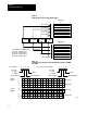
Type of I/O
I/O Rack Number
I/O Group Number
I/O Bit
I 1100
I = Input
O = Output
PLC3, PLC5, PLC5/250 Example