
USER MANUAL Manual

Configuring Your Block I/O
Chapter 3
3-5
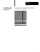
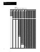
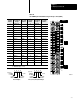
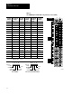
Rack Address Switch Position
PLC3
Rack
Number
PLC5/250
Rack
Number
PLC5
Rack
Number
PLC2
Rack
Number
1771SN
Rack
Number
1747SN
Rack
Number
123456
PLC3
Rack
Number
PLC5/250
Rack
Number
PLC5
Rack
Number
PLC2
Rack
Number
1771SN
Rack
Number
1747SN
Rack
Number
Rack 44 1 0 0 1 0 0
Rack 45 1 0 0 1 0 1
Rack 46 1 0 0 1 1 0
Rack 47 1 0 0 1 1 1
Rack 50 1 0 1 0 0 0
Rack 51 1 0 1 0 0 1
Rack 52 1 0 1 0 1 0
Rack 53 1 0 1 0 1 1
Rack 54 1 0 1 1 0 0
Rack 55 1 0 1 1 0 1
Rack 56 1 0 1 1 1 0
Rack 57 1 0 1 1 1 1
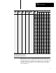
Rack 60 1 1 0 0 0 0
Rack 61 1 1 0 0 0 1
Rack 62 1 1 0 0 1 0
Rack 63 1 1 0 0 1 1
Rack 64 1 1 0 1 0 0
Rack 65 1 1 0 1 0 1
Rack 66 1 1 0 1 1 0
Rack 67 1 1 0 1 1 1
Rack 70 1 1 1 0 0 0
Rack 71 1 1 1 0 0 1
Rack 72 1 1 1 0 1 0
Rack 73 1 1 1 0 1 1
Rack 74 1 1 1 1 0 0
Rack 75 1 1 1 1 0 1
Rack 76 1 1 1 1 1 0
Not Valid 1 1 1 1 1 1
Rack
address 77 is an illegal configuration.
PLC5/1
1 processors can scan rack 03.
PLC5/15 and PLC5/20 processors can scan racks 0103.
PLC5/25 and PLC5/30 processors can scan racks 0107.
PLC5/40 and PLC5/40L processors can scan racks 0117.
PLC5/60 and PLC5/60L processors can scan racks 0127.
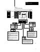
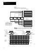
Each block uses 2 words of output image table memory and 2 words of
input image table memory. Each block occupies 1/4 rack of data table, with
4 blocks comprising 1 logical rack. Image table usage for one assigned
rack number is shown in Figure 3.3. An example of image table usage is
shown in Figure 3.4.