
USER MANUAL Manual
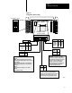

Configuring Your Block I/O
Chapter 3
3-3
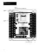
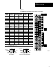
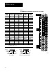
Figure 3.2
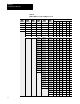
Configuration
Switch Settings
6
OFF OFF
OFF ON
ON OFF
ON ON
8
NO OFF
YES ON
5
00
01
02
03
04
05
06
07
10
11
12
13
14
15
COM
RACK
ADDR
87654321
CONFIGURATION
SWITCHES
00
01
02
03
04
05
06
07
10
11
12
13
14
15
+VDC
L
(Top View of Switch)
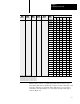
Configuration
Switch
Rack Address Switch
ON
ON
8
7
654321
134256
10932I
7
0 TO 1
2 TO 3
4 TO 5
6 TO 7
INPUT
OUTPUT
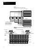
PLC5
This switch not used.
PLC2
OFF When module does not contain the
highest numbered I/O group for the associated
rack number.
PLC3
This switch must always be set to OFF."
ON When module does contain the highest
numbered I/O group for the associated rack
number.
Last Rack Switch 5
CAUTION: Set switch 3 to the ON
position to deenergize outputs wired to
this module when a fault is detected. If
switch 3 is set to the OFF position,
outputs connected to this module
remain in their last state when a fault
occurs and machine motion may
continue after fault detection.
Processor Restart Lockout (PRL) Switch 4
When PRL is enabled (on), the programmable
controller cannot automatically start up the module'
s
communications if the power has been cycled to
either the module or the programmable controller
Last State Switch 3
Disabled OFF
Enabled ON
4
PRL
Latch
Reset
OFF
ON
3
57.6kbps
115.2kbps
230.4kbps
Unused
1 2
OFF
ON
OFF
ON
OFF
OFF
ON
ON
L
AST
STATE
BAUD RATE
Last
Rack
I/O Group
Set to OFF