Block I/O Cat. No.
Important User Information Because of the variety of uses for the products described in this publication, those responsible for the application and use of this control equipment must satisfy themselves that all necessary steps have been taken to assure that each application and use meets all performance and safety requirements, including any applicable laws, regulations, codes and standards. The illustrations, charts, sample programs and layout examples shown in this guide are intended solely for example.
Table of Contents Using This Manual . . . . . . . . . . . . . . . . . . . . . . . . . . . . . . . P 1 Purpose of Manual . . . . . . . . . . . . . . . . . . . . . . . . . . . . . . . . . . . Audience . . . . . . . . . . . . . . . . . . . . . . . . . . . . . . . . . . . . . . . . . . Vocabulary . . . . . . . . . . . . . . . . . . . . . . . . . . . . . . . . . . . . . . . . Manual Organization . . . . . . . . . . . . . . . . . . . . . . . . . . . . . . . . . About Block I/O . . . . . . . . . . . . . . . . .
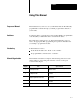
Preface Using This Manual Purpose of Manual This manual shows you how to use your block I/O with an Allen–Bradley programmable controller. It helps you install, program and troubleshoot your module. Audience You must be able to program and operate an Allen–Bradley programmable controller (PLC) to make efficient use of block I/O modules. We assume that you know how to do this in this manual.
Preface Using This Manual About Block I/O Block I/O consists of small, self–contained remote I/O devices complete with power supply, programmable controller interface, input/output connections and signal conditioning circuitry. This publication covers the 1791–IOBW and –IOVW block I/O modules. The 1791–IOBW has 32 sinking inputs and 32 sourcing outputs; the 1791–IOVW has 32 sourcing inputs and 32 sinking outputs. In all other aspects, they are identical.
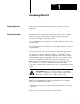
Chapter 1 Introducing Block I/O Chapter Objectives In this chapter you will learn what block I/O is, its features, and how it functions. General Description Block I/O consists of small, self-contained remote I/O devices complete with power supply, programmable controller interface, input/output connections and signal conditioning circuitry. The 1791-IOBW 24V dc module has 32 sink input channels, and 32 source output channels.
Chapter 1 Introducing Block I/O Figure 1.
Chapter 1 Introducing Block I/O Status Indicators - Bi-color LED indicators provide power, active, communication and fuse blown indications. An LED array provides input/output status.
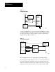
Chapter 1 Introducing Block I/O Figure 1.2 Sinking Input Example +V Block I/O Field Device Field Device dc Power Supply Sinking Input V 10826 I Sourcing outputs have the power bussed in the block. When the output is on, current is supplied to the field control device, which sinks the current. The field circuit and the equipment remain at ground potential until the output is turned on. Refer to Figure 1.3. Figure 1.
Chapter 1 Introducing Block I/O Figure 1.4 Sourcing Input Example Block I/O +V dc Power Supply V Field Device Input dc Common Bus 10917 I In sinking outputs (Figure 1.5), the current flow is reversed. The dc common is bussed on the module and the current is sourced from the field device being actuated. When an output is turned on, the output switch in the module sinks the circuit, causing current to flow from the +V bus through the field device to the module. Figure 1.
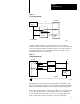
Chapter 1 Introducing Block I/O Figure 1.6 Block I/O Connection in a PLC System Blocks are daisy chained to a programmable controller or scanner. Programmable Controller or Scanner Block I/O each block is 1/4 I/O rack.
Chapter 2 Installing Block I/O Chapter Objectives In this chapter you will learn how to mount the block, how to connect the remote I/O link, how to connect the input and output wiring to the block, and how to terminate the remote I/O link.
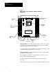
Chapter 2 Installing Block I/O Installing the Block I/O Mounting dimensions for the block I/O module are shown in Figure 2.1. Mount the blocks horizontally with a minimum of 2” between blocks. This air gap is necessary to maintain proper cooling air flow through the block. Figure 2.1 Mounting Dimensions for the Block I/O Module (Cat. No. 1791 IOBW and IOVW) 6.15 (156.21) 4.8 (122.0) 0.67 (17.105) 8 7 6 5 4 3 2 1 CONFIGURATION SWITCHES RACK ADDR Inches (Millimeters) POWER ACTIVE COMM FUSE 6.54 (166.
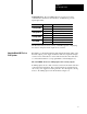
Chapter 2 Installing Block I/O Figure 2.2 Clearance Required for Block I/O Modules 2 (50.8) 2 (50.8) 2 (50.8) Inches (Millimeters) 2 (50.8) Connecting Wiring 10919 I Connections to the block I/O module are made to the removable terminal blocks on each side of the module. Input connections are on the left side, and output connections are on the right side. The input terminal block is keyed differently from the output terminal block to prevent incorrect insertion.
Chapter 2 Installing Block I/O Table 2.
Chapter 2 Installing Block I/O Table 2.B 1791 IOBW Output Terminal Wiring for Groups 0 and 1 (TRM2) Terminal Number Output Assignment Group 1 PLC SLC Terminal Number Output Assignment Group 0 PLC SLC N.C.
Chapter 2 Installing Block I/O Table 2.
Chapter 2 Installing Block I/O Table 2.D 1791 IOVW Output Terminal Wiring for Groups 0 and 1 (TRM2) Terminal Number Output Assignment Group 1 PLC SLC Terminal Number SLC Output Assignment Group 0 PLC SLC N.C.
Chapter 2 Installing Block I/O Power Supply Requirements An external 24V dc (+10/-25%) power supply is required to power the block. Total current required to power the block is equal to 100mA. In addition, the external power supply should have current limiting capabilities. The voltage range must not exceed 18.0-26.4V dc. Wiring Requirements Wiring cable requirements are shown in Table 2.F. Table 2.
Chapter 2 Installing Block I/O Remote I/O Link Wiring Blocks must be wired in series as shown in Figure 2.4. Do not attempt to wire any block in parallel. The number of blocks used depends not only on the user requirements but also on the system used. Figure 2.4 Series Connection for Block I/O Using PLC 2, PLC 3 or PLC 5 Family Programmable Controllers To Programmable Controller, remote I/O adapter or Scanner Module 1 I/O Rack 1 I/O Rack Install terminating resistor on last block.
Chapter 2 Installing Block I/O Termination Resistor A termination resistor must be used on the last block in the series. A 150 ohm and 82 ohm termination resistors are built into the unit. To select the termination resistor, position the switch to the desired position as shown in Figure 2.5. Figure 2.
Chapter 2 Installing Block I/O Compatibility of 1771 I/O Products with Extended Node Operation Certain products are not compatible with extended node capabilities obtained with the use of 82 ohm terminators. The following table lists those products that are not compatible.
Chapter 3 Configuring Your Block I/O Chapter Objectives In this chapter you will learn how to configure your block I/O when used with PLC family programmable controllers. This includes the following: setting the configuration switches addressing the block I/O To configure your block I/O for SLC family processors, refer to the user manual for the 1747-SN scanner module. ATTENTION: This module is not compatible with the 1747-DSN distributed I/O scanner module.
Chapter 3 Configuring Your Block I/O Figure 3.1 Switch Setting Locations (1791 IOBW shown) Configuration Switches 8 COM 7 6 5 4 3 2 1 +VDC 00 02 02 03 06 07 04 05 RACK ADDR 10 06 07 POWER ACTIVE COMM FUSE 11 12 Rack Address Switches 03 OUTPUT INPUT 04 05 L 00 01 CONFIGURATION SWITCHES 01 13 10 11 12 13 14 14 15 15 16 16 17 1791 IOBW NC COM 64 POINT 24V DC DISTRIBUTED I/O MODULE 00 01 CONFIGURATION SWITCHES 02 03 BAUD RATE 04 05 1 57.6K BPS 115.2KBPS 230.
Chapter 3 Configuring Your Block I/O Figure 3.2 Configuration Switch Settings Rack Address Switch COM ON 6 5 4 3 2 1 00 01 02 03 04 05 06 07 10 11 12 13 14 15 8 7 6 5 4 3 2 1 CONFIGURATION SWITCHES RACK ADDR INPUT OUTPUT Configuration Switch +VDC L 00 01 02 03 04 05 06 07 10 11 12 13 14 15 (Top View of Switch) 7 6 5 4 3 2 Set to OFF 8 I/O Group 0 TO 1 2 TO 3 4 TO 5 6 TO 7 Last Rack NO YES 6 OFF OFF ON ON 7 OFF ON OFF ON BAUD RATE 1 57.6kbps 115.2kbps 230.
Chapter 3 Configuring Your Block I/O Table 3.
Chapter 3 Configuring Your Block I/O 1747 SN Rack Number 1771 SN Rack Number PLC 2 Rack Number PLC 5 Rack Number PLC 5/250 Rack Number PLC 3 Rack Number 6 5 4 3 2 1 Rack 44 1 0 0 1 0 0 Rack 45 1 0 0 1 0 1 Rack 46 1 0 0 1 1 0 Rack 47 1 0 0 1 1 1 Rack 50 1 0 1 0 0 0 Rack 51 1 0 1 0 0 1 Rack 52 1 0 1 0 1 0 Rack 53 1 0 1 0 1 1 Rack 54 1 0 1 1 0 0 Rack 55 1 0 1 1 0 1 Rack 56 1 0 1 1 1 0 Rack 57 1 0 1 1 1 1 Rack 60 1
Chapter 3 Configuring Your Block I/O Figure 3.
Chapter 3 Configuring Your Block I/O Table 3.
Chapter 3 Configuring Your Block I/O Table 3.C 1791 IOBW Output Terminal Addressing for Groups 0 and 1 (TRM2) Output Assignment Group 0 Program Address OUTPUT N.C.
Chapter 3 Configuring Your Block I/O Table 3.
Chapter 3 Configuring Your Block I/O Table 3.E 1791 IOVW Output Terminal Addressing for Groups 0 and 1 (TRM2) Output Assignment Group 0 Program Address OUTPUT +VDC 1 N.C.
Chapter 4 Troubleshooting Chapter Objectives In this chapter you will learn about the indicators on the block I/O module, and how to use them to troubleshoot the unit. Indicators Each block I/O module has LED indicators (Figure 4.1) which provide indication of specific functions. Each module has the following: Status Indicators - Indicators are provided for power, active, communication and fuse blown indications. An LED array provides input/output status.
Chapter 4 Troubleshooting Figure 4.
Chapter 4 Troubleshooting Table 4.A Troubleshooting Chart Indication POWER ( (green) ) COMM (green) ACTIVE (green/red) FUSE (red) Probable Cause Corrective Action Green I/O status on/off Normal indication None required Off No 24V dc power connected, or hardware fault. Check 24V dc power to block Solid green Normal indication module is communicating with the programmable controller None required Off No communication with adapter, scanner etc. Check that power LED is on.
Chapter 4 Troubleshooting Summary 4-4 4. Replace the blown fuse with a 5.0A slow blow fuse. 5. Reinstall cover and secure with four screws removed in step 2. 6. Reapply power to the module.
Appendix A Specifications General Specifications External power Range: 18 to 26.4V dc 100mA @ 24V dc; initial surge 2.0A for 10ms Power Dissipation 15.1 Watts (maximum); 7.6 Watts (typical) Thermal Dissipation 51.8 BTU/hr (maximum); 25.9 BTU/hr (typical) Remote I/O Isolation 850V dc (transformer) for 1 second Interconnect cable length (PLC or SLC) RIO: 57.6K 115.2K 230.
Appendix A Specifications Output Specifications A-2 Number of outputs 32 (2 groups of 16) Output type 1791-IOBW - Source; 1791-IOVW - Sink Maximum output voltage range 18.0 to 26.4V dc @ 300mA resistive Maximum on-state voltage drop 1.5V dc @ 25oC at rated current Maximum on-state current 300mA per point Minimum on-state current 5mA Maximum output current per output group 2.4A continuous Maximum surge current 1.0A for 25ms, 1 pulse per second max. Maximum off-state voltage 26.
Index Symbols **Empty**, 1 3 B baud rate, 3 1, 3 3 C compatibility, 1 1 extended node numbers, 2 11 configuration switches, 3 3 setting, 3 1 connection, in a PLC system, 1 6 connections, wiring, 2 3 D description, P 2, 1 1 IOBX, 1 3 IOVW, 1 4 dimensions, mounting, 2 2 E extended node capability, 2 10 F fuses, removing and replacing, 4 3 G group address, 3 1, 3 3 I image table usage, 3 5 indicators I/O status array, 1 3 locations, 4 2 status, 1 3 status reported, 4 1 input, sourcing, 1 4 input termin
I–2 Index switch settings, 3 3 T cable requirements, 2 8 IOBX input terminals, 0 and 1, 2 4 IOBX output terminals, 0 and 1, 2 5 IOVX input terminals, 0 and 1, 2 6 IOVX output terminals, 0 and 1, 2 7 remote I/O link, 2 8 termination resistor installation, 2 10 internal, 3 1 wiring connections, 2 3 troubleshooting chart, 4 3 wiring terminals, 1 2 W wiring block designations, 2 7
Allen Bradley, a Rockwell Automation Business, has been helping its customers improve productivity and quality for more than 90 years. We design, manufacture and support a broad range of automation products worldwide. They include logic processors, power and motion control devices, operator interfaces, sensors and a variety of software. Rockwell is one of the worlds leading technology companies. Worldwide representation.