
Manual
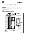
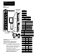
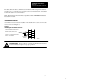

SW1
SW2
Open cover to
access switches
1
30
Position = 1Position = 0
End View of Switch
12391–I
87654321
01
87654321
01
Default Switch
Settings = 0
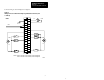
NOTE: Set switch SW2–3 to 0 if this rack will have a
unique address (not complemented). If this rack
address is a duplicate of another I/O block or
chassis, set the switch to 1 for primary or 0 for
complementary. Refer to Table C for the
complementary I/O rack address.
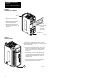
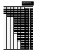
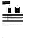
1791-16A0
120V
ac INPUT
INPUT INPUT
00
01
02
03
04
05
06
07
10
11
12
13
14
15
16
17
Only block I/O modules with all inputs or
all outputs can use complementary I/O.
ATTENTION: Cycle power to the module after
setting the switches.
Series A block I/O modules do not support
complementary I/O. If using series A
modules, set switch SW2–3 to 0.
Installation Instructions
Block I/O
Cat. No. 1791-16A0 Series B
6
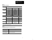
Figure 6
Switch
Settings
SW2–8
Not use
Not use
d
SW2–7
Not used
SW2–6 Last I/O Group
0 Not last rack
1 Last rack
SW2–5
Processor
Restart/Lockout (PRL)
0 Processor Restart
1 Processor Lockout
SW2–4 Hold Last State
0 Reset Outputs
1 Hold Last State
SW2–3 Complementary I/O
1
0 Non-Complemented System
0 Complementary Rack
1
1 Primary Rack
1
1
See note.
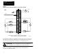
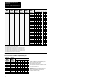
Communication Rate
SW2–2 SW2–1 Bits/s
0 0 57.6 K
0 1 115.2 K
1 0 230.4 K
1 1 230.4 K
Starting Quarter
SW1–2 SW1–1
Module
Group
0 0 0 (1st)
0 1 2 (2nd)
1 0 4 (3rd)
1 1 6 (4th)