
Manual

Installation Instructions
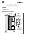
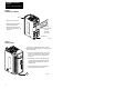
Block I/O
Cat. No. 1791-16A0 Series B
5
5
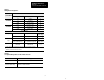
T
able
A
Wiring
Block Designations
is
1791–16A0 Series B
Connect
i
on
s
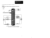
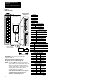
Designation Description Terminal No.
Power
Connections
L1 ac hot 1
Power
Connections
N
ac neutral 3
GND Chassis ground 2
1
Remote I/O
Connections
BLU Blue wire – RIO 6
Remote I/O
Connections
CLR
Clear wire – RIO 8
SHD Shield – RIO 7
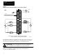
I/O Connections
Input in 00 thru in 07 Input 00 thru 07
16, 18, 20, 22,
24, 26, 28, 30
COM 1 L2/N Input Common 10, 12, 14
2
COM 2 L2/N Input Common 9, 11, 13
3
Input
PLC: in 10 thru in 17
SLC: in 08 thru in 15
PLC: Input 10 thru Input 17
SLC: Input 08 thru Input 15
15, 17, 19, 21,
23, 25, 27, 29
Not used
For internal test only; not for
customer use.
4, 5
1
Connect chassis ground to equipment grounding stud. These are not internally connected.
2
T
erminals 10, 12 and 14 are internally connected.
3
T
erminals 9, 11 and 13 are internally connected.
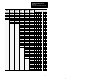
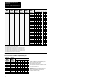
T
able B
Acceptable
W
iring Cables for Block I/O Connection
Use Cable Type
Remote I/O link Belden 9463
Input and output wiring
Up to 14AWG (2mm
2
) stranded with
3/64 inch (1.2mm) insulation