Installation Instructions PROFIBUS DP Digital Base Terminal Block CompactBlock LDX I/O (Cat. Nos. 1790P-T8BV8V, -T8BV8B, -T0W6) What This Document Describes This document describes how to install your PROFIBUS DP CompactBlock LDX I/O.
Important User Information Because of the variety of uses for the products described in this publication, those responsible for the application and use of these products must satisfy themselves that all necessary steps have been taken to assure that each application and use meets all performance and safety requirements, including any applicable laws, regulations, codes and standards.
WARNING ! ATTENTION Identifies information about practices or circumstances that can cause an explosion in a hazardous environment, which may lead to personal injury or death, property damage, or economic loss. Identifies information about practices or circumstances that can lead to personal injury or death, property damage, or economic loss. ! IMPORTANT Identifies information that is critical for successful application and understanding of the product.
Environment and Enclosure This equipment is intended for use in a Pollution Degree 2 industrial environment, in overvoltage Category II applications (as defined in IEC publication 60664-1), at altitudes up to 2000 meters without derating. This equipment is considered Group 1, Class A industrial equipment according to IEC/CISPR Publication 11.
Installing CompactBlock LDX I/O Follow these steps to install the base block: 1. Set the station address on the base block. 2. Mount the base block. 3. Mount the optional expansion blocks. 4. Wire the terminal blocks. 5. Connect the PROFIBUS connector. 6. Connect power to the block. These steps are explained in detail in the following procedures. Set the Station Address on the Base Block To set the station address, adjust the switches on the front of the base block.
Mount the Base Block You can mount the base block to a panel or DIN rail. We recommend that you ground the panel or DIN rail before mounting the base block. WARNING ! When used in a Class I, Division 2, hazardous location, this equipment must be mounted in a suitable enclosure with the proper wiring method that complies with the governing electrical codes. Panel Mounting 1. Place the base block against the panel where you want to mount it. 2. Gently pull and position the expansion cover to the left.
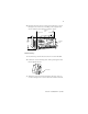
5. Replace the base block on the panel and place a screw through each of the two mounting holes. Tighten the screws until the base block is firmly in place. 109.5 mm 4.3 in Expansion Cover 42.5 mm 1.7 in DIN Rail Mounting 1. Hook the top slot of the base block over the DIN Rail. 2. Pull down on the locking lever while pressing the base block against the rail. f Locking Lever 3. When the base block is flush against the rail, push up on the locking lever to secure the base block to the rail.
Mount the Optional Expansion Blocks The analog base blocks can accommodate a maximum of two discrete expansion blocks. The RTD and thermocouple base blocks do not support any expansion blocks. IMPORTANT Mount the expansion block by connecting it to a previously-installed CompactBlock LDX I/O base or expansion block.
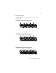
Wire the Terminal Block The following figures show the wiring information for the terminal blocks. 1790P-T8BV8V Input/Output Base Block Wiring Diagram IN0 IN4 1 IN6 3 5 2 4 11 9 6 8 IN7 19 18 16 14 OUT1 COM IN3 OUT6 17 15 13 12 10 IN5 OUT4 OUT2 VDC 7 IN1 OUT0 COM IN2 20 OUT5 OUT3 GND OUT7 • Sinking inputs - wire COM (pin 9) to Field Power (-) GND Sourcing inputs - wire COM (pin 9) to Field Power (+) 24V dc Note: both COM (pins 9 and 10) are internally connected.
Wire and Connect the PROFIBUS DP Terminal Connector Follow these procedures when connecting the PROFIBUS DP terminal connector to the base block. WARNING ! If you connect or disconnect the PROFIBUS cable with power applied to this module or any device on the network, an electrical arc can occur. This could cause an explosion in hazardous location installations. Be sure that power is removed or the area is nonhazardous before proceeding.
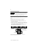
Once you have properly wired the connector, attach it to the base block as shown below. Use the locking screws on the connector to fasten it to the base block. Module Power Connector (underneath module) Green - GND Black - COM Red - +24Vdc PROFIBUS Connector Connect Power to the Block To apply power to the block, refer to the above illustration.
Troubleshoot with the Indicators The base block has the following indicators: • module status • network status • I/O status Mod/Net Status Indicator LED Indicator: Status: Description: Module Status Solid Red Unrecoverable fault in base block Flashing Red Unrecoverable fault in expansion unit Solid Green Normal operation - OK Off No power Status: Description: LED Indicator: Network Status Solid Red Unrecoverable communication fault Flashing Red Recoverable communication fault Solid
PROFIBUS DP Digital Base Terminal Block Specifications The following table contains specifications that are common to all of the base blocks in this document. Individual base block specifications are detailed after this table.
PROFIBUS DP Specifications Network Protocol PROFIBUS-DP (EN50170) • Communication of the slave with a Class 1 master • Communication of the slave with a Class 2 master Redundancy Not supported Repeater Control RS485 signal Signal Implementation Type DPC31 Freeze Mode Supported Sync Mode Supported Auto Baud Rate Supported Fail Safe Mode Supported1 Station Type FMS Support Indicators Slave Not supported 1 red/green module status 1 red/green network status Number of nodes 100 maximum - rotary switch type
DC Input/Output Combination Base Block Specifications 1790P-T8BV8V, -T8BV8B INPUT SPECIFICATIONS Inputs per base block 8 points non-isolated, sinking or sourcing On-state voltage 9.6V dc minimum 24V dc nominal 28.8V dc maximum On-state current 8mA maximum per point @ 28.8V dc Off-state voltage 5V dc maximum Nominal input impedance 4.
General Specifications PROFIBUS Power Supply voltage - 24V dc nominal Voltage range - 19.2-28.8V dc Power dissipation - 1.2W maximum @ 28.8V dc Field Power Supply voltage - 24V dc nominal Voltage range - 10-28.8V dc Power dissipation - 3.22W @ 28.8V dc Isolation I/O to logic: photocoupler isolation Isolation voltage: 1250V ac rms PROFIBUS to logic: non-isolated PROFIBUS power: non-isolated Wiring Terminal block (M3.
General Specifications PROFIBUS Power Supply voltage - 24V dc nominal Voltage range - 19.2-28.8V dc Power dissipation - 1.2W maximum @ 28.8V dc Field Power Supply voltage - 24V dc nominal Voltage range - 19.2-28.8V dc Power dissipation - 1.7W @ 28.8V dc Isolation I/O to logic: photocoupler isolation Isolation voltage: 1250V ac rms Wiring Terminal block (M3.
The following information applies when operating this equipment in hazardous locations: Informations sur l’utilisation de cet équipement en environnements dangereux : Products marked “CL I, DIV 2, GP A, B, C, D” are suitable for use in Class I Division 2 Groups A, B, C, D, Hazardous Locations and nonhazardous locations only. Each product is supplied with markings on the rating nameplate indicating the hazardous location temperature code.
Publication 1790-IN009B-EN-P - April 2003
Publication 1790-IN009B-EN-P - April 2003 Supersedes Publication 1790-IN009A-EN-P - February 2002 PN957782-06 © 2003 Rockwell Automation.