
Instruction Manual


Publication 1790-UM002A-EN-P
Diagnostics and Troubleshooting 4-5
Channel LED
Indicator Operation
Individual channel LED indicator operation is shown in the following
table.
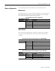
Table 4.4 Word Bit Position
Word Bit Description
1514131211109876543210
4 Not Used S11 S10 S9 S8 Not Used S3 S2 S1 S0
Table 4.5 Word/Bit Description
Word Decimal Bit Description
Read Word 4
Bits 00-03 Underrange for individual channels. Bit 00 corresponds to input
channel 0, bit 01 corresponds to input channel 1 and so on.
When set (1), the input signal is below the input channel’s
minimum range
Bits 04-07 Not used: Set to 0
Bit 08-11 Overrange for individual channels. Bit 08 corresponds to input
channel 0, bit 09 corresponds to input channel 1 and so on.
When set (1), the input signal is above the input channel’s
maximum range, or open RTD is detected
Bit 12-15 Not used: Set to 0
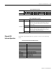
Table 4.6 Individual Channel LEDs Indicator
I/O Channel LED Status Indicator
Status: Description
Flashing Green/Red Power up
Off Off line
Red On line and no field power
Red DeviceNet connection and no field power
Flashing Red Field power and open wire
Green Field power and valid input
Flashing Red Input over range, open input
Flashing Red Input under range
Flashing Red Recoverable fault