
Instruction Manual

Publication 1790-UM002A-EN-P
Module Data, Status, and Channel Configuration for DeviceNet 3-3
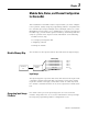
Over-Range Flag Bits (S8 to S11)
Under-range bits for channels 0 through 3 are contained in word 4, bits
8-11. When set (1), the over-range flag bit indicates an RTD temperature
that is greater than the maximum allowed temperature, a resistance input
that is greater than the maximum allowed resistance for the module or an
open channel is detected. The module automatically resets (0) the bit
when the data value is again within the normal operating range.
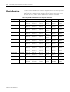
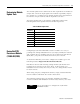
Data Format
RTD/resistance data is presented in engineering units x1. The engineering
units data format represents real temperature or resistance data provided
by the module. RTD data is reported in either degrees C or degrees F.
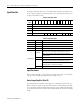
Table 3.3 RTD Data Format
RTD Input Type Range
Data Format
Engineering Units x1
0.1°C 0.1°F
100Ω Platinum 385 -200 to +850°C -2000 to +8500 -3280 to +15620
200Ω Platinum 385 -200 to +850°C -2000 to +8500 -3280 to +15620
500Ω Platinum 385 -200 to +650°C -2000 to +6500 -3280 to +12020
100Ω Platinum 3916 -200 to +640°C -2000 to +6400 -3280 to +1184
200Ω Platinum 3916 -200 to +640°C -2000 to +6400 -3280 to +1184
500Ω Platinum 3916 -200 to +640°C -2000 to +6400 -3280 to +1184
100Ω Nickel -60 to +250°C -600 to +2500 -760 to +4820
120Ω Nickel -80 to +260°C -800 to +2600 -1120 to +5000
200 Nickel -60C to 250°C -600 to +2500 -760 to +4820
500 Nickel -60 to 250°C -600 to +2500 -760 to +4820
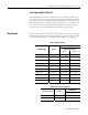
Table 3.4 Resistance Data Format
Resistance Input Range
Data Format
Engineering Units x1
Resistance 100mΩ 1 to 625Ω 10 to 6250
Resistance 10mΩ 1 to 327Ω 100 to 32700