CompactBlock LDX RTD/Resistance Input Module 1790D-4R0, 1790D-T4R0, 1790P-T4R0 User Manual
Important User Information Because of the variety of uses for the products described in this publication, those responsible for the application and use of these products must satisfy themselves that all necessary steps have been taken to assure that each application and use meets all performance and safety requirements, including any applicable laws, regulations, codes and standards.
IMPORTANT Rockwell Automation Support Identifies information that is critical for successful application and understanding of the product. Before you contact Rockwell Automation for technical assistance, we suggest you please review the troubleshooting information contained in this publication first. If the problem persists, call your local Rockwell Automation representative or contact Rockwell Automation in one of the following ways: Phone Internet United States/Canada 1.440.646.
Table of Contents Chapter 1 Overview General Description Hardware Features . System Overview . . Chapter Summary . . . . . . . . . . . . . . . . . . . . . . . . . . . . . . . . . . . . . . . . . . . . . . . . . . . . . . . . . . . . . . . . . . . . . . . . . . . . . . . . . . . . . . . . . . . . . . . . . . . . . . . . . . . . . . . . . . . . . . 1-1 1-3 1-4 1-6 Before You Begin . . . . . . Power Requirements . . . . General Considerations . . Mounting . . . . . . . . . . . .
Table of Contents ii Appendix B Two’s Complement Binary Numbers Positive Decimal Values . . . . . . . . . . . . . . . . . . . . . . . . . . B-1 Negative Decimal Values . . . . . . . . . . . . . . . . . . . . . . . . . . B-2 Appendix C Module Configuration for PROFIBUS Publication 1790-UM002A-EN-P - May 2002 Configure PROFIBUS RTD/Resistance Modules (1790P-T4R0) . . . . . . . . . . . . . . . . . . . . . . . . . . . . . . . . . .
Chapter 1 Overview This chapter describes the four-channel 1790D-4R0/T4R0 RTD/resistance Input module and explains how the controller reads resistance temperature detector (RTD) or direct resistance-initiated analog input data from the module.
1-2 Overview The module supports the following filter frequencies: • 10 Hz • 25 Hz • 50 Hz • 60 Hz • 100 Hz • 250 Hz • 500 Hz The module uses five input words for data and status bits. Module configuration is stored in the module memory. Configuration for 1790D-(T)4R0 is done via RSNetWorx for DeviceNet™ programming software. See Chapter 3, Module Data, Status, and Channel Configuration, for details on module configuration. Configuration for 1790P-T4R0 is done via PROFIBUS configuration software.
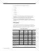
Overview 1-3 Resister Device Compatibility The following table lists the specifications for the resistance devices that you can use with the module. Table 1.2 Resistance Device Specifications Resistance Type Range Scaling (Counts) Resolution* Resistance 100mΩ 1 to 650Ω 10 to 6250 Resistance 10mΩ 1 to 327Ω 100 to 32700 Accuracy (0 to 55°C)** 100mΩ +1.25Ω 10Ω +0.
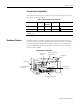
1-4 Overview 1790P-T4R0 PROFIBUS DP Module Node Address Switches Module and Network Status Indicators Panel Mount Hole DIN Rail Slot PROFIBUS Network Connector RTD/resistance Channel Indicators RTD/resistance Connections (Terminal block) PROFIBUS Connector Module Power Connector (underneath module) 31341-M General Diagnostic Features Module, network, and channel LEDs help you identify the source of problems that may occur during power-up or during normal channel operation.
Overview 1-5 Once a channel is properly configured and enabled, the module continuously converts the RTD or resistance input to a value within the range selected for that channel. Each time the module reads an input channel, it tests the data for a fault (over- or under-range or open-circuit condition). If it detects a fault, the module sets a unique bit in the channel status word. See Input Data File on page 3-2.
1-6 Overview Chapter Summary Publication 1790-UM002A-EN-P In this chapter, you learned about the 1790D/4R0/T4R0 and 1790P-TR40 RTD/resistance modules. See Chapter 2 to learn how to install and wire the modules.
Chapter 2 Installation and Wiring Before You Begin This chapter tells you how to: • determine the power requirements for the modules • avoid electrostatic damage • install the module • wire the module’s terminal block Power Requirements 1790D-4R0/T4R0 The module receives system power from the DeviceNet network. An auxiliary field supply provides power for the RTD/resistance channels. Table 2.
2-2 Installation and Wiring General Considerations The modules are suitable for use in a commercial or light industrial environment when installed in accordance with these instructions. Specifically, this equipment is intended for use in clean, dry environments (Pollution degree 2(1)) and to circuits not exceeding Over Voltage Category II(2) (IEC 60664-1).(3) Hazardous Location Considerations This equipment is suitable for use in Class I, Division 2, Groups A, B, C, D or non-hazardous locations only.
Installation and Wiring 2-3 Environment and Enclosure This equipment is intended for use in a Pollution Degree 2 industrial environment, in overvoltage Category II applications (as defined in IEC publication 60664-1), at altitudes up to 2000 meters without derating. This equipment is considered Group 1, Class A industrial equipment according to IEC/CISPR Publication 11.
2-4 Installation and Wiring Preventing Electrostatic Discharge ATTENTION ÿ WARNING ÿ This equipment is sensitive to electrostatic discharge, which can cause internal damage and affect normal operation. Follow these guidelines when you handle this equipment: • Touch a grounded object to discharge potential static. • Wear an approved grounding wriststrap. • Do not touch connectors or pins on component boards. • Do not touch circuit components inside the equipment.
Installation and Wiring 2-5 Protecting the Circuit Board from Contamination The printed circuit boards of analog modules must be protected from dirt, oil, moisture, and other airborne contaminants. To protect these boards, the system must be installed in an enclosure suitable for the environment. The interior of the enclosure should be kept clean and the enclosure door should be kept closed whenever possible. Installing CompactBlock LDX I/O Follow these steps to install the block: 1.
2-6 Installation and Wiring Set the Station Address on the 1790P-T4R0 PROFIBUS DP Base Block To set the station address, adjust the switches on the front of the base block. The two switches are most significant digit (MSD) and least significant digit (LSD). The switches can be set between 00 and 99. The rotary switches are read at base block power up only. Example: Node Address is set at 26 43230 Mounting Mount the Base Block You can mount the base block to a panel or DIN rail.
Installation and Wiring 2-7 5. Replace the block on the panel and place a screw through each of the two mounting holes. Tighten the screws until the block is firmly in place. 95 mm 3.74 in k LDX CompactBloc 1790-16BVOX EXPANSION UNIT 41 mm 1.6 in Expansion Cover ER 16 INPUTS-DCPOW 7 7 0 0 43242 DIN Rail Mounting 1. Hook the top slot of the block over the DIN Rail. 2. Pull down on the locking lever while pressing the block against the rail. ÿ Locking Lever 43243 3.
2-8 Installation and Wiring Connect the DeviceNet Cable to the 1790D-4R0/T4R0 Base Block Follow these procedures when connecting the DeviceNet cable to the base block. The required DeviceNet connector is not supplied with the block - you must purchase it separately.
Installation and Wiring 2-9 Connect the PROFIBUS DP Terminal Connector to the 1790P-T4R0 Base Block Follow these procedures to connect the PROFIBUS DP terminal connector to the base block. WARNING ÿ If you connect or disconnect the PROFIBUS cable with power applied to this module or any device on the network, an electrical arc can occur. This could cause an explosion in hazardous location installations. Be sure that power is removed or the area is nonhazardous before proceeding.
2-10 Installation and Wiring Once you have properly wired the connector, attach it to the base block as shown below. Use the locking screws on the connector to fasten it to the base block. Module Power Connector (underneath module) PROFIBUS Connector Green - GRD Black - COM Red - +24V dc 43249 Connect Power to the 1790P-T4R0 Block To apply power to the block, refer to the above illustration.
Installation and Wiring Field Wiring Connections 2-11 System Wiring Guidelines Consider the following when wiring your system: General • This product is intended to be mounted to a well-grounded mounting surface such as a metal panel. Additional grounding connections from the module’s mounting tabs or DIN rail (if used) are not required unless the mounting surface cannot be grounded.
2-12 Installation and Wiring RTD Wiring Considerations Because the operating principle of the RTD module is based on the measurement of resistance, take special care when selecting your input cable. For 2-wire or 3-wire configurations, select a cable that has a consistent impedance throughout its entire length. Cable specifications are noted below. Table 2.
Installation and Wiring 2-13 To insure that the lead values match as closely as possible: • Keep lead resistance as small as possible. • Use quality cable that has a small tolerance impedance rating. • Use a heavy-gauge lead wire which has less resistance per foot. Wire Size and Terminal Screw Torque Each terminal accepts up to two wires with the following restrictions: Table 2.
2-14 Installation and Wiring To wire your module follow these steps. 1. At each end of the cable, strip some casing to expose the individual wires. 2. Trim the signal wires to 2-inch (5 cm) lengths. Strip about 3/16 inch (5 mm) of insulation away to expose the end of the wire. ATTENTION ÿ Be careful when stripping wires. Wire fragments that fall into a module could cause damage at power up. 3.
Installation and Wiring 2-15 2-Wire RTD Configuration Add Jumper Cable Shield (to Ground) RTD EXC RTD EXC CHO_A CHO_B Return Return COM 43251 3-Wire RTD Configuration Cable Shield (to Ground) RTD EXC CHO_A RTD EXC Sense Sense Return Return CHO_B COM 43252 4-Wire RTD Configuration Cable Shield (to Ground) RTD EXC Leave this sensor wire open RTD EXC CHO_A CHO_B COM Sense Sense Return Return 43253 Wiring Resistance Devices (Potentiometers) Potentiometer wiring requires the same type of
2-16 Installation and Wiring 2-Wire Potentiometer Interconnection Add Jumper Cable Shield (to Ground) Potentiometer RTD EXC CHO_A CHO_B Return COM Add Jumper Cable Shield (to Ground) Potentiometer RTD EXC CHO_A CHO_B Return COM 43254 TIP The potentiometer wiper arm can be connected to either the EXC or return terminal depending on whether you want increasing or decreasing resistance.
Installation and Wiring 2-17 Wiring the Terminal Blocks The following figures show how to wire the terminal blocks.
2-18 Installation and Wiring Chapter Summary Publication 1790-UM002A-EN-P In this chapter, you learned how to install and wire your modules. See Chapter 3 to learn about module data, status, and channel configuration with DeviceNet.
Chapter 3 Module Data, Status, and Channel Configuration for DeviceNet After installation of the RTD/resistance input module, you must configure it for operation, usually using the programming software compatible with the controller (for example, RSLogix 500™ or RSLogix 5000™) or scanner (RSNetWorx for DeviceNet). Once configuration is complete and reflected in ladder logic, you will need to get the module up and running and then verify its operation.
3-2 Module Data, Status, and Channel Configuration for DeviceNet Input Data File The input data table lets you access RTD input module read data for use in the control program, via word and bit access. The data table structure is shown in the tables below. Table 3.
Module Data, Status, and Channel Configuration for DeviceNet 3-3 Over-Range Flag Bits (S8 to S11) Under-range bits for channels 0 through 3 are contained in word 4, bits 8-11. When set (1), the over-range flag bit indicates an RTD temperature that is greater than the maximum allowed temperature, a resistance input that is greater than the maximum allowed resistance for the module or an open channel is detected.
3-4 Module Data, Status, and Channel Configuration for DeviceNet The module scales input data to the actual temperature values for the selected RTD type per RTD standard. It expresses temperatures in 0.1 degree units, either degrees C or degrees F, depending on which temperature scale is selected. For resistance inputs, the module expresses resistance in 0.1Ω units for the 100mΩ scale and in 0.01Ω units for the 10mΩ scale. Negative temperatures are returned in 16-bit two’s complement binary format.
Module Data, Status, and Channel Configuration for DeviceNet 3-5 Common mode noise rejection for the module is better than 110 dB at 50 Hz (50 Hz filter) and 60 Hz (60 Hz filter). The module performs well in the presence of common mode noise. Improper earth ground can be a source of common mode noise. NOTE Channel Step Response Transducer power supply noise, transducer circuit noise, and process variable irregularities can also be sources of common mode noise.
3-6 Module Data, Status, and Channel Configuration for DeviceNet Channel Cutoff Frequency The channel cutoff frequency (-3 dB) is the point on the input channel frequency response curve where frequency components of the input signal are passed with 3 dB of attenuation. The following table shows cutoff frequencies for the supported filters. Table 3.6 Filter Frequency vs. Channel Cutoff Frequency Filter Frequency Channel Cutoff Frequency 10 Hz 2.62 Hz 25 Hz 6.55 Hz 50 Hz 13.1 Hz 60 Hz 15.
Module Data, Status, and Channel Configuration for DeviceNet 3-7 Frequency Response Graphs 10 Hz Input Filter Frequency 50 Hz Input Filter Frequency 0 –3 dB –20 –20 –40 –40 –60 –60 –80 –80 Gain (dB) Gain (dB) 0 -100 -120 -100 -120 -140 -140 -160 -160 -180 -180 - 200 - 200 0 10 30 20 50 40 60 0 Frequency (Hz) 2.62 Hz –3 dB 50 13.
3-8 Module Data, Status, and Channel Configuration for DeviceNet Effective Resolution The table below identifies the number of significant bits used to represent the input data for each available filter frequency. The number of significant bits is defined as the number of bits that will have little or no jitter due to noise, and is used in defining the effective resolution. Table 3.
Module Data, Status, and Channel Configuration for DeviceNet Determining Module Update Time 3-9 The module update time is defined as the time required for the module to sample and convert the input signals. The module sequentially samples the channels in a continuous loop. Module update time is dependent on the number of input channels and the input filter selection. The fastest update time occurs with the 500Hz filter enabled. The following table shows update times for all filter frequencies. Table 3.
3-10 Module Data, Status, and Channel Configuration for DeviceNet Configure DeviceNet RTD/Resistance Modules Using RSNetWorx Online Browse Button Publication 1790-UM002A-EN-P Following the steps below to configure 1790D-4R0/T4R0 RTD/resistance modules. 1. Open RSNetWorx for DeviceNet. 2. Using the selections on the left of the window below, construct you system. (If your network is up, just click on the Online Browse button.
Module Data, Status, and Channel Configuration for DeviceNet 3-11 3. After setting up your system, double-click on the module you want to configure. (If you are online, upload the configuration and existing parameters from the module display.) A window similar to the following appears. Click the device Parameters tab to display the screen in which you can set parameters. RTD/resistance modules will have parameters similar to the following.
3-12 Module Data, Status, and Channel Configuration for DeviceNet Module configuration parameters include Temperature Units/Notch Filter frequency, RTD/resistance Input type and Autobaud. Select the desired temperature units (in degrees C or F) and notch filter frequency. ALL four channels will be configured identically. Select the RTD/ resistance input type for each channel from the dropdown list. Select to have Autobaud either Enabled or Disabled.
Module Data, Status, and Channel Configuration for DeviceNet 3-13 Once module configuration is complete, click either the Download or Apply button and click Yes for the popup question. Then click OK to close the module properties window. RTD/resistance module parameters may be monitored real time. The most convenient way to monitor module parameters is to: a. Click the Groups checkbox. b. Close the No Group Specified folder c. Open the I/O Input Values and I/O Input Status folders. d.
3-14 Module Data, Status, and Channel Configuration for DeviceNet Chapter Summary Publication 1790-UM002A-EN-P In this chapter, you learned how to setup and configure your module. See Chapter 4 to learn how to troubleshoot using the module indicators.
Chapter 4 Diagnostics and Troubleshooting This chapter describes module troubleshooting, containing information on: • safety considerations when troubleshooting • module vs. channel operation • the module’s diagnostic features • critical vs. non-critical errors • module condition data • contacting Rockwell Automation for assistance Safety Considerations Safety considerations are an important element of proper troubleshooting procedures.
4-2 Diagnostics and Troubleshooting Stand Clear of the Equipment When troubleshooting any system problem, have all personnel remain clear of the equipment. The problem could be intermittent, and sudden unexpected machine motion could occur. Have someone ready to operate an emergency stop switch in case it becomes necessary to shut off power.
Diagnostics and Troubleshooting Power-up Diagnostics 4-3 Power-up diagnostics includes module status and network status. Module Status At module power-up, a series of internal diagnostic tests are performed. These diagnostic tests must be successfully completed. The following table shows module status LED indictor operation. Table 4.
4-4 Diagnostics and Troubleshooting Channel Diagnostics When an input channel is enabled, the module performs a diagnostic check to see that the channel has been properly configured. In addition, the channel is tested on every scan for configuration errors, over-range and under-range, and broken input conditions. Non-critical module errors are typically recoverable. Channel errors (over-range or under-range errors) are non-critical.
Diagnostics and Troubleshooting 4-5 Table 4.4 Word Bit Position Word Bit Description 15 14 13 12 11 10 9 4 Not Used 8 7 S11 S10 S9 S8 6 5 4 Not Used 3 2 1 0 S3 S2 S1 S0 Table 4.5 Word/Bit Description Word Read Word 4 Channel LED Indicator Operation Decimal Bit Description Bits 00-03 Underrange for individual channels. Bit 00 corresponds to input channel 0, bit 01 corresponds to input channel 1 and so on.
4-6 Diagnostics and Troubleshooting Contacting Rockwell Automation If you need to contact Rockwell Automation for assistance, please have the following information available when you call: • a clear statement of the problem, including a description of what the system is actually doing. Note the LED state; also note input and output image words for the module.
Appendix A Specifications Environmental Specifications Environmental Specifications Operating Temperature 0 to 55°C (32 to 131°F) IEC 60068-2-1 (Test Ad, Operating Cold), IEC 60068-2-2 (Test Bd, Operating Dry Heat), IEC 60068-2-14 (Test Nb, Operating Thermal Shock) Storage Temperature -40 to 85°C (-40 to 185°F) IEC 60068-2-1 (Test Ab, Un-packaged Non-operating Cold), IEC 60068-2-2 (Test Bb, Un-packaged Non-operating Dry Heat), IEC 60068-2-14 (Test Na, Un-packaged Non-operating Thermal Shock) Relative
A-2 Specifications DeviceNet Specifications PROFIBUS DP Specifications Publication 1790-UM002A-EN-P Specification Value Network protocol I/O Slave messaging: - Poll command - Bit Strobe command - Cyclic command - COS command Network length 500 meters maximum @ 125Kbps 100 meters maximum @ 500Kbps Indicators 1 red/green module status 1 red/green network status Number of nodes 64 maximum - rotary switch type node address setting Communication rate 125Kbps, 250Kbps, 500Kbps - auto baud rate sel
Specifications A-3 General Specifications ÿþýþüûúùø÷þöõôõöûóõòýñ Wiring Category 21 Product Certifications (when product or packaging is marked) c-UL-us UL Listed for Class I, Division 2 Group A,B,C,D Hazardous Locations, certified for U.S. and Canada CE2 European Union 89/336/EEC EMC Directive, compliant with: EN 50081-2; Industrial Emissions EN 50082-2; Industrial Immunity EN61326; Meas./Control/Lab.
A-4 Specifications RTD/Resistance Specifications Publication 1790-UM002A-EN-P RTD/resistance Specifications Inputs per module 4 channel, RTD/Resistance Input Input Range 1-625 Sensors Supported Sensor Type Degree Counts Resolution Resistance 100mΩ 1 to 625Ω 10 to 6250 100mΩ Resistance 10mΩ 1 to 327Ω 100 to 32700 10mΩ 100ohm Pt/α =0.00385 -200 to +850°C -2000 to +8500 0.1°C 200ohm Pt/α =0.00385 -200 to +850°C -2000 to +8500 0.1°C 500ohm Pt/α =0.00385 -200 to +650°C -2000 to +6500 0.1°C 100ohm Pt/α =0.
Appendix B Two’s Complement Binary Numbers The processor memory stores 16-bit binary numbers. Two’s complement binary is used when performing mathematical calculations internal to the processor. Analog input values from the RTD/resistance module are returned to the processor in 16-bit two’s complement binary format. For positive numbers, the binary notation and two’s complement binary notation are identical.
B-2 Two’s Complement Binary Numbers Negative Decimal Values In two’s complement notation, the far left position is always 1 for negative values. The equivalent decimal value of the binary number is obtained by subtracting the value of the far left position, 32768, from the sum of the values of the other positions. In the figure below (all positions are 1), the value is 32767 - 32768 = -1.
Appendix C Module Configuration for PROFIBUS After installation of the RTD/resistance module, you must configure it for operation, usually by using the programming software compatible with the controller or scanner. This appendix includes PROFIBUS configuration information. Chapter 3 contains detailed information on module parameters and performance.
C-2 Module Configuration for PROFIBUS If it’s not already installed, add the RTD/resistance module GSD file from the dropdown menu. Access: 1. Library>Add GSD. 2. Click File>New. If the PROFIBUS devices pane is closed, choose: 3. View>Library to open the pane. If the on-line Browse pane is closed, choose: 4. View>On-line to open the pane. You should now be ready to set up your system. 5. Expand the Master and Slaves folders in the PROFIBUS Device pane.
Module Configuration for PROFIBUS C-3 Choose the Master communication parameters You can add modules to the network by: 1. Selecting slaves from the PROFIBUS Device pane 2. Dragging and dropping them to the network pane Or, if online, by performing a search for slaves See the following screens for an outline of this procedure. First, configure the network search properties. Second, search for slave modules.
C-4 Module Configuration for PROFIBUS Highlight the slave, right click the mouse and select GSD Files>1790-T4R0.gsd 7. Highlight the slave from the Online Browse pane and drag and drop it to the Network pane. The slave station number should be set. (If you dragged and dropped from the PROFIBUS Device pane, you must set the station number.) Station number should be set Highlight and drag and drop the slave device to the Network pane 8.
Module Configuration for PROFIBUS The 1790P-T4R0 module produces 5 words of data. C-5 The produced 5 words will appear in the processor input data table. 9. Click the Ext. Prms tab. This is where the parameters that can be set for the slave RTD/ resistance module are configured. On this screen, you see all the parameters for the module. These include watchdog time, temperature units, filter frequency, and input RTD/ resistance type.
C-6 Module Configuration for PROFIBUS Select the temperature units (degrees C or F). All four channels will be configured identically. Select the filter cutoff frequency desired. All four channels will be configured identically. Select the RTD/ resistance input type for each channel from the dropdown list. 10. When configuration is complete, click the OK button to close the module properties screen. Save the Configuration To close the configuration: 1. Choose File>Save As. 2.
Module Configuration for PROFIBUS Download the Configuration C-7 To download the configuration: 1. Verify that the processor is in Program Mode. 2. Make sure the serial communication cable is connected between the PC comm port and the scanner serial port. 3. Highlight Master in the Network pane. 4. Right click to select Connect from the menu. (Or, choose Edit>Connect). Highlight the Master and then right click to select Connect.
C-8 Module Configuration for PROFIBUS 5. Load the configuration to the Master through one of the following methods. • Right click on the Master and select Load Configuration from the menu. Or, • Select the Load configuration icon in the toolbar. If the scanner is online, the following message displays: Card is online. Do you want to load configuration. • Select Yes to load your new configuration.
Module Configuration for PROFIBUS C-9 The Net LED on the RTD/resistance module should turn solid green as should the Comm LED on the scanner. The connection should report OK.
C-10 Module Configuration for PROFIBUS Summary This appendix illustrated how to configure your PROFIBUS RTD/ resistance module with the SST PROFIBUS Configuration tool. For more information, consult your PROFIBUS network documentation, PROFIBUS scanner documentation and network configuration tool documentation.
Glossary The following terms and abbreviations are used throughout this manual. For definitions of terms not listed here refer to Allen-Bradley’s Industrial Automation Glossary, Publication AG-7.1. A/D Converter– Refers to the analog to digital converter inherent to the module. The converter produces a digital value whose magnitude is proportional to the magnitude of an analog input signal. attenuation – The reduction in the magnitude of a signal as it passes through a system.
G-2 effective resolution – The number of bits in a channel configuration word that do not vary due to noise. excitation current – A user-selectable current that the module sends through the input device to produce an analog signal that the module can process and convert to temperature (RTD) or resistance in ohms (resistance device). filter – A device that passes a signal or range of signals and eliminates all others. filter frequency – The user-selectable frequency for a digital filter.
G-3 module update time – The time required for the module to sample and convert the input signals of all enabled input channels and make the resulting data values available to the processor. multiplexer – An switching system that allows several signals to share a common A/D converter. normal mode rejection – (differential mode rejection) A logarithmic measure, in dB, of a device’s ability to reject noise signals between or among circuit signal conductors.
G-4 Notes: Publication 1790-UM002A-EN-P
How Are We Doing? Your comments on our technical publications will help us serve you better in the future. Thank you for taking the time to provide us feedback. You can complete this form and mail it back to us, visit us online at www.ab.com/manuals, or email us at RADocumentComments@ra.rockwell.com Pub. Title/Type CompactBlock LDX RTD/Resistance Input Module Cat. No. Pub. No. 1790D-(T)4R0, 1790P-T4R0 1790-UM002A-EN-P Pub. Date May 2002 Part No. 957657-66 Please complete the sections below.
PLEASE FASTEN HERE (DO NOT STAPLE) PLEASE FOLD HERE NO POSTAGE NECESSARY IF MAILED IN THE UNITED STATES BUSINESS REPLY MAIL FIRST-CLASS MAIL PERMIT NO.
Index Numbers 1790D-4R0 general description 1-1 hardware features 1-3 power requirements 2-2 1790D-T4R0 general description 1-1 hardware features 1-3 power requirements 2-2 1790P-T4R0 connecting power 2-11 general description 1-1 hardware features 1-4 power requirements 2-2 A A/D definition G-1 A/D converter 1-5 abbreviations G-1 activating devices when troubleshooting 4-1 addressing 3-1 attenuation 3-6 definition G-1 B base block mounting 2-7 broken input detection 4-4 bus interface 1-4 C channel 1-5 de
2 Index data word definition G-1 dB definition G-1 decibel. See dB.
Index wiring the modules 2-14 general considerations 2-2 set station address (PROFIBUS) 2-7 hazardous location considerations 2-3 installing CompactBlock LDX I/O 2-6 protecting circuit board 2-6 selecting a location 2-5 set node address (DeviceNet) 2-6 mounting 2-7 base block 2-7 connecting DeviceNet cable 2-9 connecting power to PROFIBUS block 2-11 connecting PROFIBUS DP connector 2-10 DIN rail mounting 2-8 panel mounting 2-7 power requirements 2-2 installing CompactBlock LDX I/O 2-6 L LED 4-1 linearity
4 Index protecting circuit board 2-6 R register configuration 3-1 resistance devices wiring 2-16 resister device compatibility 1-3 resolution definition G-3 return connections 1-5 Rockwell Automation support 3 RTD definition G-3 specifications 1-2 RTD compatibility 1-2 RTD wiring 2-13 RTD/Resistance specifications A-4 S safety circuits 4-2 safety considerations 4-1 activating devices when troubleshooting 4-1 indicator lights 4-1 program alteration 4-2 safety circuits 4-2 stand clear of equipment 4-2 sam
Publication 1790-UM002A-EN-P - May 2002 11 PN 957657-66 Copyright © 2002 Rockwell Automation. All rights reserved. Printed in the U.S.A.