Installation Instructions DeviceNet Analog Base D-Shell CompactBlock LDX I/O (Cat. Nos. 1790D-N4C0, -N0C2, -N4V0, -N0V2) What This Document Describes This document describes how to install your CompactBlock LDX™ I/O blocks.
Important User Information Because of the variety of uses for the products described in this publication, those responsible for the application and use of these products must satisfy themselves that all necessary steps have been taken to assure that each application and use meets all performance and safety requirements, including any applicable laws, regulations, codes and standards.
ATTENTION Identifies information about practices or circumstances that can lead to personal injury or death, property damage, or economic loss. ! IMPORTANT ATTENTION ! Identifies information that is critical for successful application and understanding of the product. Preventing Electrostatic Discharge This equipment is sensitive to electrostatic discharge, which can cause internal damage and affect normal operation.
ATTENTION ! Environment and Enclosure This equipment is intended for use in a Pollution Degree 2 industrial environment, in overvoltage Category II applications (as defined in IEC publication 60664-1), at altitudes up to 2000 meters without derating. This equipment is considered Group 1, Class A industrial equipment according to IEC/CISPR Publication 11.
Installing CompactBlock LDX I/O Follow these steps to install the block: 1. Set the node address on the base block. 2. Mount the base block. 3. Mount the optional expansion blocks. 4. Wire the D-Shell connectors. 5. Connect the DeviceNet cable. These steps are explained in detail in the following procedures. Set the Node Address on the Base Block Each base block comes with its internal program set for node address 63. To reset the node address, adjust the switches on the front of the block.
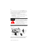
Mount the Base Block You can mount the base block to a panel or DIN rail. We recommend that you ground the panel or DIN rail before mounting the block. IMPORTANT The analog base module can accommodate a maximum of two discrete expansion modules. WARNING ! When used in a Class I, Division 2, hazardous location, this equipment must be mounted in a suitable enclosure with the proper wiring method that complies with the governing electrical codes. Panel Mounting 1.
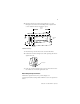
5. Replace the block on the panel and place a screw through each of the two mounting holes. Tighten the screws until the block is firmly in place. 95 mm 3.74 in 41 mm 1.6 in k LDX CompactBloc 1790-16BVOX EXPANSION UNIT 16 INPUTS-DCPOW ER Expansion Cover 7 7 0 0 DIN Rail Mounting 1. Hook the top slot of the block over the DIN Rail. 2. Pull down on the locking lever while pressing the block against the rail. f Locking Lever 3.
Beginning with the base block, you can mount your expansion blocks either horizontally or vertically: • horizontally (left to right) - add expansion blocks in an end-to-end configuration • vertically (up or down) - add expansion blocks either up or down in a back-to-back configuration. In this configuration, you must use the optional 15cm ribbon cable (1790-15CMCBL) and alternately position the blocks in a right-side up, upside-down fashion.
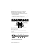
1790D-N0C2 Current Analog Input Module Wiring Diagram for D-Shell Connector +24V +24V +24V 19 18 37 16 17 35 36 CH1 CH0 15 34 13 14 33 30 31 32 11 12 GND GND GND 9 10 28 29 COM 8 27 7 26 5 6 24 25 3 4 22 23 1 2 20 21 COM • Wire pins 17, 18 and 19 to Field Power (+) 24Vdc Wire pins 35, 36 and 37 to Field Power (-) GND 1790D-N4V0 Voltage Analong Input Module Wiring Diagram for D-Shell Connector +24V +24V +24V 19 18 37 16 17 35 36 CH1 CH0 15 34 13 14 33 30 31 32
The required DeviceNet connector is not supplied with the block - you must purchase it separately.
I/O Memory Mapping 1790D-N4C0, -N4V0 Input Data File Word Bit Position 0 Not Used Analog Input Data Channel 0 1 Not Used Analog Input Data Channel 1 2 Not Used Analog Input Data Channel 2 3 Not Used Analog Input Data Channel 3 4 Not Used 15 14 13 12 11 10 9 8 7 6 5 4 3 2 1 0 S 3 S 2 S 1 S 0 Word/Bit Descriptions for 1790D-N4C0, -N4V0 Analog Input Module Word Read Word 0 Read Word 1 Read Word 2 Read Word 3 Decimal Bit Description Bits 00-11 Channel 0 input data Bi
1790D-N0C2, -N0V2 Output Data File Word Bit Position 15 14 13 12 11 10 9 8 7 6 0 Not Used Analog Output Data Channel 0 1 Not Used Analog Output Data Channel 1 5 4 3 2 1 Word/Bit Descriptions for 1790D-N0C2, -N0V2 Analog Output Module Word Write Word 0 Write Word 1 Decimal Bit Description Bits 00-11 Channel 0 output data Bits 12-15 Not used: Set to 0 Bits 00-11 Channel 1 output data Bits 12-15 Not used: Set to 0 Troubleshoot with the Indicators The 1790D I/O block has the
I/O Channel LED Status Indicator 1790D-N4V0 1790D-N4C0 Status: Description: Status: Description: Flashing Green/ Red Power up Flashing Green/ Red Power up Off Off line Off Off line Red On line and no field power Red On line and no field power Red DeviceNet connection and no field power Red DeviceNet connection and no field power Green Field power and open wire Flashing Red1 Field power and open wire (4-20mA range only)2 Green Field power and valid input Green Field power and
I/O Channel LED Status Indicator 1790D-N0V2 1790D-N0C2 Status: Description: Status: Description: Flashing Green/ Red Power up Flashing Green/ Red Power up Off Off line Off Off line Off On line and no field power Off On line and no field power Green DeviceNet connection and no field power Green DeviceNet connection and no field power Green Field power and open wire Green Field power and open wire Green Field power and valid output Green Field power and valid output Flashing
DeviceNet Analog Base D-Shell Block Specifications The following table contains specifications that are common to all of the blocks in this document. Individual base block specifications are detailed after this table.
DeviceNet Specifications Network protocol I/O Slave messaging: - Poll command - Bit Strobe command - Cyclic command - COS command Network length 500 meters maximum @ 125Kbps 100 meters maximum @ 500Kbps Indicators 1 red/green module status 1 red/green network status Number of nodes 64 maximum - rotary switch type node address setting Communication rate 125Kbps, 250Kbps, 500Kbps - auto baud rate selection Isolation Type test 1250Vac rms for 60 seconds between field power and DeviceNet (I/O to
4-Channel Analog Current Input Module Specifications 1790D-N4C0 Inputs per module 4 channel single-ended, non-isolated Input Current (software configurable) 4-20mA (default) 0-20mA Resolution 12 bits-unipolar 1/4096 maximum 3.90µA/bit (4-20mA) 4.88µA/bit (0-20mA) Converted Data Binary data 0000 to 0fff (max scale) Conversion Time 10ms/channel Overall accuracy 0.
2 Channel Analog Current Output Module Specifications 1790D-N0C2 Outputs per module 2 channel single-ended, non-isolated Output Current 0-20mA Resolution 12 bits 1/4096 maximum 4.88µA/bit Converted Data Binary data 0000 to 0fff (max scale) Conversion Time 2ms/channel Overall accuracy 0.
4 Channel Analog Voltage Input Module Specifications 1790D-N4V0 Inputs per module 4 channel single-ended, non-isolated Input Voltage 0-10V Resolution 12 bits-unipolar 1/4096 maximum 2.44mV/bit Converted Data Binary data 0000 to 0fff (max scale) Conversion Time 10ms/channel Overall accuracy 0.
2 Channel Analog Voltage Output Module Specifications 1790D-N0V2 Outputs per module 2 channel single-ended, non-isolated Output Voltage 0-10V Resolution 12 bits-unipolar 1/4096 maximum 2.44mV/bit Converted Data Binary data 0000 to 0fff (max scale) Conversion Time 2ms/channel Overall accuracy 0.2% Full scale @0°-55°C Calibration None required Allowable external output load resistance 1KΩ minimum Output Impedance 0.
The following information applies when operating this equipment in hazardous locations: Informations sur l’utilisation de cet équipement en environnements dangereux : Products marked “CL I, DIV 2, GP A, B, C, D” are suitable for use in Class I Division 2 Groups A, B, C, D, Hazardous Locations and nonhazardous locations only. Each product is supplied with markings on the rating nameplate indicating the hazardous location temperature code.
Publication 1790-IN004B-EN-P - April 2003
Publication 1790-IN004B-EN-P - April 2003
This product has been tested at an Open Device Vendors Association, Inc. (ODVA) authorized independent test laboratory and found to comply with ODVA Conformance Test. Please contact the ODVA website (http://www.odva.org) for listing of products tested by ODVA independent test labs for further details. CompactBlock LDX and RSNetWorx for DeviceNet are trademarks of Rockwell Automation. DeviceNet is a trademark of Open DeviceNet Vendor Association.