
User guide

12 DeviceNet 32 Point Digital Base Terminal Block CompactBlock LDX I/O
Publication
1790-IN014A-EN-P - March 2008
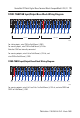
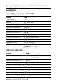
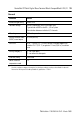
1790D-T0V32 Input/Output Base Block Wiring Diagram
For sinking outputs, wire V dc 0 and V dc 1 to Field Power (+) 24V dc, and wire GND0 and
GND1 to Field Power (-) GND.
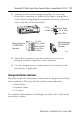
Connect the DeviceNet Cable
Follow these procedures to connect the DeviceNet cable to the base
block. The DeviceNet connector is not supplied with the base block.
You must purchase the connector separately. These are the types of
connectors you order directly from Rockwell Automation.
• 1799-DNETCON - 5-position open-style connector
• 1799-DNETSCON - 5-position open-style connector with
locking screws
• 1799-DNC5MMS - 5-position open-style to 12 mm (0.47 in.)
connector with locking screws
WARNING
If you connect or disconnect the communication cable with power applied to
this module or any device on the network, an electrical arc can occur. This
could cause an explosion in hazardous location installations.
Be sure that power is removed or the area is nonhazardous before proceeding
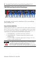
VDC0
OUT0
OUT2
OUT4
OUT6
OUT8
OUT10
OUT12
OUT14
24V
OUT16
OUT18
OUT20
OUT22
OUT24
OUT26
OUT28
OUT30
OUT1 OUT3 OUT5 OUT7 OUT9
OUT11
OUT13
OUT15
OUT17
OUT19
OUT21
OUT23
OUT25
OUT27 OUT29
OUT31
44258
GND0
GND0