
User Manual

Publication 1790-UM001A-EN-P - March 2002
B-10 PROFIBUS Modules Installation, Wiring, Module Data, Status and Channel Configuration
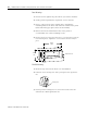
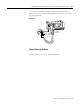
Connecting I/O Wiring
Consider the following guidelines when wiring your system:
General Guidelines
• All module commons (ANLG COM) are connected in the analog
module. The analog common (ANLG COM) is not connected to
earth ground inside the module.
• Channels are not isolated from each other.
• Do not use the analog module’s NC terminals as connection
points.
• To ensure optimum accuracy, limit overall cable impedance by
keeping your cable as short as possible. Locate the I/O system
as close to your sensors or actuators as your application will
permit.
• Use Belden™ 8761, or equivalent, shielded wire.
• Keep shield connection to ground as short as possible.
• Under normal conditions, the drain wire and shield junction
must be connected to earth ground via a panel or DIN rail
mounting screw at the analog I/O module end.
Guidelines for Input Modules
• If multiple power supplies are used with analog inputs, the
power supply commons must be connected together.
• The module does not provide loop power for analog inputs. Use
a power supply that matches the input transmitter specifications.
Guidelines for Output Modules
• Current outputs (CH0 and CH1) of the 1790P-TNOC2 module
source current that returns to COM. Load resistance for a current
output channel must remain between 0 and 600
Ω .