
User Manual

Publication 1790-UM001A-EN-P - March 2002
PROFIBUS Modules Installation, Wiring, Module Data, Status and Channel Configuration B-9
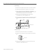
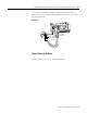
Once you have properly wired the connector, attach it to the base
block as shown in . Use the locking screws on the connector to fasten
it to the base block.
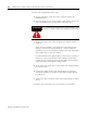
Figure B.2
Connect Power to the Block
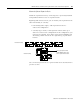
To apply power to the block, refer to Figure B.2.
Green - GND
Black - COM
Red - +24V dc
PROFIBUS
Connector