
User Manual

Publication 1790-UM001A-EN-P - March 2002
Module Diagnostics and Troubleshooting 5-5
Analog Input Module Error
Definition Table
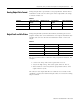
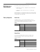
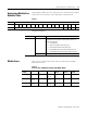
Analog input module errors are expressed on a channel bases in input
read word 4. The structure of the status data is shown below.
Word/Bit Descriptions
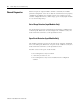
Module Errors
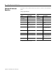
Table 5.4 lists possible errors that cause the analog input module
status bits to be set.
Table 5.3
Word Bit Position
1514131211109876543210
4 Not used S3 S2 S1 S0
Word Decimal Bit Description
Read Word 4 Bits 00-03 Status bits for individual channels - Bit 00 corresponds to input
channel 0, bit 01 corresponds to input channel 1 and so on.
When set (1) indicates:
• No field power
• Open wire (4-20mA current input only)
• Under range (4-20mA current input only)
• Recoverable module fault (whole channel to be set)
• Unrecoverable module fault (whole channel to be set)
Bits 04-15 Not used: Set to 0
Table 5.4
Status Bit Table 1790D-N4CO/-TN4CO, 1790D-N4VO/-TN4VO
Range
Setting
Underrange In Range Overrange Open
Circuit
Short
Circuit
No Field
Power
4-20mA <4mA
Set
Not set >20mA
Not set
Set Set Set
0-20mA <0mA
Not set
Not set >20mA
Not set
Not set Not set Set
0-10V dc <0V dc
Not set
Not set >10V
Not set
Not set Not set Set