
User Manual

Publication 1790-UM001A-EN-P - March 2002
3-6 Module Data, Status, and Channel Configuration for Analog Input Modules
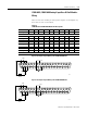
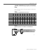
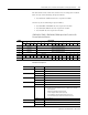
The data table below shows the structure for an analog base module
with two (2) 16-input 1790-16BV0X/-T16BV0X discrete expansion
modules.
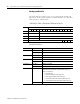
1790D-N4C0/-TN4C0, 1790D-N4V0/-TN4V0 Input Data File with 32-Bit
Discrete Expansion Modules
Word/Bit Descriptions
Word Bit Position
1514131211109876543210
0 Not Used Analog Input Data Channel 0
1 Not Used Analog Input Data Channel 1
2 Not Used Analog Input Data Channel 2
3 Not Used Analog Input Data Channel 3
4 Not Used S3 S2 S1 S0
5 D15D14D13D12D11D10D9D8D7D6D5D4D3D2D1D0
6 D31 D30 D29 D28 D27 D26 D25 D24 D23 D22 D21 D20 D19 D18 D17 D16
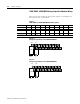
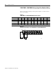
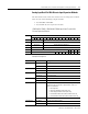
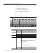
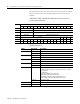
Word Decimal Bit Description
Read Word 0 Bits 00-11 Channel 0 input data
Bits 12-15 Not used: Set to 0
Read Word 1 Bits 00-11 Channel 1 input data
Bits 12-15 Not used: Set to 0
Read Word 2 Bits 00-11 Channel 2 input data
Bits 12-15 Not used: Set to 0
Read Word 3 Bits 00-11 Channel 3 input data
Bits 12-15 Not used: Set to 0
Read Word 4 Bits 00-03 Status bits for individual channels - Bit 00 corresponds to input
channel 0, bit 01 corresponds to input channel 1 and so on. When
set (1) indicates:
No field power
Open wire (4-20mA current input only)
Under range (4-20mA current input only)
Recoverable module fault (whole channel to be set)
Unrecoverable module fault (whole channel to be set)
Bits 04-15 Not used: Set to 0
Read Word 5 Bits 00-15 First discrete Input expansion data
Read Word 6 Bits 00-15 Second discrete Input expansion data