
User Manual

Publication 1790-UM001A-EN-P - March 2002
Installation and Wiring 2-17
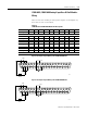
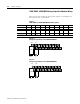
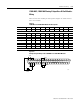
1790D-N0C2, 1790D-N0V2 Analog 2 Output Base D-Shell Modules
Wiring
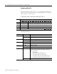
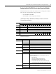
Table 2.6 lists the module pin descriptions. Figure 2.6 shows how to
wire each module.
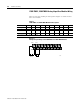
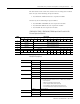
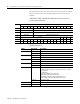
Figure 2.6
Example of Input Wiring to the 1790D-N0C2 and 1790D-N0V2 Modules
Table 2.6
1790D-N0C2 and 1790D-N0V2 Module Pin Descriptions
Pin Number 12345678910
Description: NC NC NC NC NC NC NC NC NC CH1
Pin Number: 11 12 13 14 15 16 17 18 19 20
Description: NC CH0 NC NC NC NC +24V +24V +24V NC
Pin Number 21 22 23 24 25 26 27 28 29 30
Description: NC NC NC NC NC NC NC COM NC COM
Pin Number: 31 32 33 34 35 36 37
Description: NC NC NC NC GND GND GND
NC = No Connect +24V = Field Power (+) 24V dc GND = Field Power (-) GND
L
COM
CH0
24V dc
GND
+24V
+ –
+ –
43225