
User Manual

Publication 1790-UM001A-EN-P - March 2002
2-16 Installation and Wiring
1790D-TN4C0, 1790D-TN4V0 Analog 4 Input Base Modules Wiring
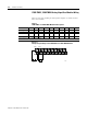
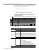
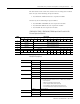
Table 2.5 lists the module pin descriptions. Figure 2.4 and Figure 2.5
show how to wire each module.
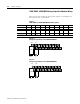
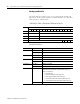
Figure 2.4
Example of Input Wiring to the 1790D-TN4C0 Module
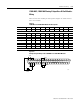
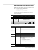
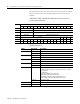
Figure 2.5
Example of Input Wiring to the 1790D-TN4V0 Module
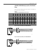
Table 2.5
1790D-TN4C0 and 1790D-TN4V0 Module Pin Descriptions
Pin Number 12345678910
Description: +24V GND CH0 COM CH1 COM CH2 COM CH3 COM
Pin Number: 11 12 13 14 15 16 17 18 19 20
Description: NC NC NC NC NC NC NC NC NC NC
+24V = Field Power (+) 24V dc GND = Field Power (-) GND
mA
COM
CH0
24V dc
GND
+24V
+ –
+
–
V
COM
CH0
24V dc
GND
+24V
+ –
+
–