
Instruction Manual

9
Publication 1790-IN003A-EN-P - April 2001
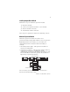
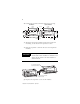
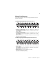
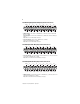
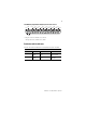
1790-0W8X Relay Output Module Wiring Diagram for D-Shell Connector
• Wire pins 18 and 19 to Field Power (+) 24Vdc
Wire pins 36 and 37 to Field Power (-) GND
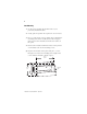
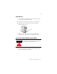
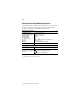
Troubleshoot with the Indicators
Use the I/O status indicators to troubleshoot your module:.
I/O Status Indicators
Function: LED Color: Module Illumination: Condition:
Outputs Each output:
Green
None
Green
Output not energized
Output energized
Inputs Each Input:
Green
None
Green
No valid input
Valid input
19
18
17
16
15
14
13
12
11
10
9
8
7
6
5
4
3
2
1
37
36
35
34
33
32
31
30
29
28
27
26
25
24
23
22
21
20
+24V
CH0
COM0
CH1
COM1
CH2
COM2
CH3
COM3
CH4
COM4
CH5
COM5
CH6
COM6
CH7
COM7
GND
GND
+24V