Installation Instructions Digital Expansion D-Shell Module CompactBlock LDX I/O (Cat. Nos. 1790-16BV0X, -8BV8VX, -8BV8BX, -0B16X, -0V16X, -0W8X) What This Document Describes This document describes how to install your CompactBlock LDX I/O expansion modules.
European Union Directive Compliance If this product has the CE mark, it is approved for installation within the European Union and EEA regions and it has been designed and tested to meet the following directives.
Installing CompactBlock LDX I/O Follow these steps to install the expansion module: 1. Mount the module. 2. Connect an expansion module to a base module. 3. Wire the D-Shell connectors. 4. Troubleshoot with the indicators. These steps are explained in detail in the following sections.
Panel Mounting 1. On the panel, position the module next to your previously-installed module. 2. Gently pull and position the expansion covers inward. 3. Place a center punch, nail or similar device through the mounting holes in the module (lower left and upper right corners of the module) and make two marks on the panel. 4. Remove the module and drill two holes in the panel to accommodate each of the mounting screws. 5.
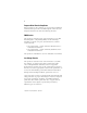
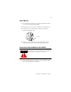
DIN Rail Mounting 1. On the DIN rail, postion the expansion module next to your previously-installed module. 2. Hook the top of slot of the module over the DIN rail. 3. Pull down on the locking lever while pressing the module against the rail. f Locking Lever 4. Push up on the locking lever when module is flush against the rail. This secures the module to the rail . Connecting an Expansion Module to a Base Module ATTENTION Expansion modules should not be installed when power is applied to the base.
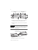
2. Position the expansion module with proper spacing. Base Module Expansion Module 95 mm 3.74 in LDX CompactBlock 1790-16BVOX EXPANSION UNIT 41 mm 1.6 in 95 mm 3.74 in 25 mm 1 in LDX CompactBlock 1790-16BVOX EXPANSION UNIT DC INPUTS 0 7 DC OUTPUTS 0 41 mm 1.6 in 16 INPUTS-DCPOWER 16 INPUTS-DCPOWER 7 0 DC INPUTS 7 0 DC OUTPUTS Expansion cover 7 Expansion cover 3. Mount the expansion module using panel or DIN rail mounting, as described in the previous section. 4.
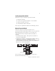
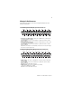
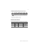
Wiring the D-Shell Connectors The following figures show the wiring information for the D-Shell connectors.
1790-8BV8BX Input/Output Module Wiring Diagram for D-Shell Connector COM0 I1 I3 I0 19 18 37 17 16 35 36 I6 I4 15 34 I7 I5 I2 13 14 33 12 31 32 11 30 O0 O2 O4 O6 COM2 O1 O3 O5 O7 9 10 28 29 8 27 7 26 5 6 24 25 3 4 22 23 1 2 20 21 COM1 COM1 COM1 COM1 COM1 COM3 COM3 COM3 COM3 COM1 COM1 COM1 COM1 COM3 COM3 COM3 COM3 COM3 • Sinking inputs - wire Com 1 to Field Power (+) 24V dc, wire Com 0 to Field Power (-) GND Sourcing inputs - wire Com1 to Field Power (-) GND, wire Com 0 to
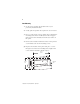
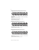
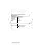
1790-0W8X Relay Output Module Wiring Diagram for D-Shell Connector CH3 CH4 CH0 CH5 CH6 CH1 CH7 CH2 COM0 COM1 COM2 COM3 COM4 COM5 COM6 COM7 +24V +24V 19 18 37 17 36 16 35 15 34 13 14 33 32 12 31 11 30 9 10 29 28 8 27 7 26 5 6 25 24 3 4 23 22 1 2 21 20 GND GND • Wire pins 18 and 19 to Field Power (+) 24Vdc Wire pins 36 and 37 to Field Power (-) GND Troubleshoot with the Indicators Use the I/O status indicators to troubleshoot your module:.
Digital Expansion D-Shell Module Specifications The following table contains specifications that are common to all of the expansion modules in this document. Individual module specifications are detailed after this table. Environmental Specifications Operating Temperature Non-Operating Temperature Relative Humidity Operating Altitude Shock Operating Non-operating Vibration Mounting Dimensions 0 to 55°C (32 to 140°F) -40 to 85°C (-40 to 185°F) 5-90% non-condensing 2000m 10g 30g 2g @ 10-500Hz, 0.
Universal DC Input Module Specifications 1790-16BVOX Inputs per module 16 points, sinking or sourcing On-state voltage 9.6V dc minimum 24V dc nominal 28.8V dc maximum Off-state voltage 5.0V dc maximum On-state current 8mA maximum per channel @ 28.8V dc Nominal input impedance 4.
DC Input/Output Combination Module Specifications 1790-8BV8VX, -8BV8BX INPUT SPECIFICATIONS Inputs per module 8 points non-isolated, sinking or sourcing On-state voltage 9.6V dc minimum 24V dc nominal 28.8V dc maximum On-state current 8mA maximum per point @ 28.8V dc Off-state voltage 5V dc maximum Nominal input impedance 4.
General Specifications Isolation I/O to logic: photocoupler isolation Isolation voltage: 1250V ac rms Wiring 37-pin D-Shell connector DC Output Module Specifications 1790-OV16X and -OB16X Outputs per module 16 points non-isolated, sinking: 1790-0V16X 16 points non-isolated, sourcing: 1790-0B16X On-state voltage 10V dc minimum 24V dc nominal 28.8V dc maximum On-state voltage drop 0.5V dc maximum On-state current 1mA minimum per channel Off-state voltage 28.8V dc maximum Off-state leakage 0.
AC/DC Relay Output Module Specifications 1790-OW8X Relay type Form A, normally open Single pole, single throw Output voltage range (load dependent) 5-24V dc @ 2.0A resistive 30V ac @ 2.0A resistive Output current rating (at rated power) 2.0A @ 5-24V dc resistive 2.0A @ 30V dc resistive Minimum load 100µA, 100mV dc per input Maximum on-state voltage drop 0.5V @ 2.
C-UL and UL Hazardous Location Approval Due to the modular nature of a programmable control system, the product with the highest temperature rating determines the overall temperature code rating of a programmable control system in a Class I, Division 2, location. The temperature code rating is marked on the product label as shown.
The following warnings apply to products having C-UL and UL certification for use in hazardous locations. WARNING: Explosion Hazard Substitution of components may impair suitability for Class I, Division 2. Do not replace components unless power has been switched off or the area is known to be non-hazardous. Do not disconnect equipment unless power has been switched off or the area is known to be non-hazardous.