Installation Instructions DeviceNet Base RTD and Thermocouple CompactBlock LDX I/O (Cat. Nos. 1790D-4R0, -4T0, -T4R0, -T4T0) What This Document Describes This document describes how to install your CompactBlock LDX™ I/O blocks.
Important User Information Because of the variety of uses for the products described in this publication, those responsible for the application and use of these products must satisfy themselves that all necessary steps have been taken to assure that each application and use meets all performance and safety requirements, including any applicable laws, regulations, codes and standards.
ATTENTION Identifies information about practices or circumstances that can lead to personal injury or death, property damage, or economic loss. ! IMPORTANT ATTENTION ! Identifies information that is critical for successful application and understanding of the product. Preventing Electrostatic Discharge This equipment is sensitive to electrostatic discharge, which can cause internal damage and affect normal operation.
ATTENTION ! Environment and Enclosure This equipment is intended for use in a Pollution Degree 2 industrial environment, in overvoltage Category II applications (as defined in IEC publication 60664-1), at altitudes up to 2000 meters without derating. This equipment is considered Group 1, Class A industrial equipment according to IEC/CISPR Publication 11.
Installing CompactBlock LDX I/O Follow these steps to install the block: 1. Set the node address on the base block. 2. Mount the base block. 3. Wire the terminal blocks. 4. Connect field wiring. 5. Connect the DeviceNet cable. These steps are explained in detail in the following procedures. Set the Node Address on the Base Block Each base block comes with its internal program set for node address 63. To reset the node address, adjust the switches on the front of the block.
Mount the Base Block You can mount the base block to a panel or DIN rail. We recommend that you ground the panel or DIN rail before mounting the block. IMPORTANT The RTD and thermocouple base blocks do not support any expansion blocks. WARNING ! When used in a Class I, Division 2, hazardous location, this equipment must be mounted in a suitable enclosure with the proper wiring method that complies with the governing electrical codes. Panel Mounting 1.
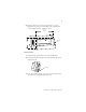
5. Replace the block on the panel and place a screw through each of the two mounting holes. Tighten the screws until the block is firmly in place. 95 mm 3.74 in 41 mm 1.6 in k LDX CompactBloc 1790-16BVOX EXPANSION UNIT 16 INPUTS-DCPOW ER Expansion Cover 7 7 0 0 DIN Rail Mounting 1. Hook the top slot of the block over the DIN Rail. 2. Pull down on the locking lever while pressing the block against the rail. f Locking Lever 3.
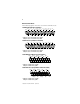
Wire the Terminal Blocks The following figures show how to wire the terminal blocks.
Connect Field Wiring System Wiring Guidelines Follow these guidelines when wiring your system: • use shielded, twisted pair wire to ensure proper operation and high immunity to electrical noise • to limit noise, locate RTD and resistance device signal wires as far away as possible from power lines, load lines and other sources of electrical noise, such as hard-contact switches, relays and AC motor drives • under normal conditions, the drain wire and shield junction should be connected to earth ground, v
IMPORTANT The RTD block requires three wires to compensate for lead resistance error. We recommend that you do not use 2-wire RTDs if long cable runs are required, as it reduces the accuracy of the system. However, if a 2-wire configuration is required, reduce the effect of the lead wire resistance by using a lower-gauge wire for the cable (for example, use AWG #16 instead of AWG #24). The block’s terminal strip accepts AWG #14 gauge wire.
To ensure that the lead values match as closely as possible: • keep lead resistance as small as possible and less than 25 ohms • use quality cable that has a small tolerance impedance rating • use a heavy-gauge lead wire which has less resistance per foot RTD Wiring Configurations Three configurations of RTDs can be connected to the blocks: • 2-wire RTD, which is composed of an RTD EXC (excitation) lead wire and a RTN (return) wire • 3-wire RTD, which is composed of a Sense and 2 RTD lead wires (RTD EX
3-Wire RTD Configuration Cable Shield (to Ground) CH0_A CH0_B COM RTD EXC Sense Return RTD EXC Sense Return 4-Wire RTD Configuration Leave this sensor wire open Cable Shield (to Ground) CH0_A CH0_B COM RTD EXC RTD EXC Sense Sense Return Return Wiring Resistance Devices (Potentiometers) Potentiometer wiring requires the same type of cable as that for the RTD.
3-Wire Potentiometer Interconnection The potentiometer wiper arm can be connected to either the EXC or return terminal, depending on whether you want increasing or decreasing resistance.
Connect the DeviceNet Cable Follow these procedures when connecting the DeviceNet cable to the base block. The required DeviceNet connector is not supplied with the block - you must purchase it separately.
Once you have properly wired the drop line to the connector, attach the connector to the block. If applicable, use the locking screws on the connector to fasten it to the block.
1790D-4T0, -T4T0 Input Data File Word Bit Position 15 14 13 12 11 10 9 8 7 6 5 0 Thermocouple Input Data Channel 0 1 Thermocouple Input Data Channel 1 2 Thermocouple Input Data Channel 2 3 4 3 2 1 0 S3 S2 S1 S0 Thermocouple Input Data Channel 3 4 Not Used S11 S10 S9 S8 Not Used Word/Bit Descriptions for 1790D-4T0, -T4T0 Thermocouple Module Word Decimal Bit Description Read Word 0 Bits 00-15 Channel 0 input data Read Word 1 Bits 00-15 Channel 1 input data Read
Troubleshoot with the Indicators The 1790D I/O block has the following indicators: • module status • network status • I/O status Mod/Net Status Indicator LED Indicator: Status: Description: Module Status Solid Red Unrecoverable fault in base unit Flashing Red Recoverable fault LED Indicator: Network Status Solid Green Normal operation - OK Flashing Green Standby Off No power Status: Description: Solid Red Unrecoverable communication fault Flashing Red Recoverable communication fault
DeviceNet RTD and Thermocouple Base Block Specifications The following table contains specifications that are common to all of the blocks in this document. Individual base block specifications are detailed after this table.
DeviceNet Specifications Network protocol I/O Slave messaging: - Poll command - Bit Strobe command - Cyclic command - COS command Network length 500 meters maximum @ 125Kbps 100 meters maximum @ 500Kbps Indicators 1 red/green module status 1 red/green network status Number of nodes 64 maximum - rotary switch type node address setting Communication rate 125Kbps, 250Kbps, 500Kbps - auto baud rate selection Isolation Type test 1250Vac rms for 60 seconds between field power and DeviceNet (I/O to lo
4-Channel Input RTD Base Module Specifications 1790D-4R0, 1790D-T4R0 Inputs per module 4 channel, RTD/Resistance Input Input Range 1-625 Sensors Supported Sensor Type Degree Counts Resolution Resistance 100mΩ 1 to 625Ω 10 to 6250 100mΩ Resistance 10mΩ 1 to 327Ω 100 to 10mΩ 32700 100ohm Pt/α =0.00385 -200 to -2000 to 0.1°C +850°C +8500 200ohm Pt/α =0.00385 -200 to -2000 to 0.1°C +850°C +8500 500ohm Pt/α =0.00385 -200 to -2000 to 0.1°C +650°C +6500 100ohm Pt/α =0.003916 -200 to -2000 to 0.
General Specifications DeviceNet Power Field Power Isolation Indicators Wiring 1790D-4R0 1790D-T4R0 Supply voltage - 24V dc nominal Voltage range - 11-28.8V dc Power dissipation - 1.2W maximum @ 28.8V dc Supply Voltage - 24Vdc nominal Voltage Range - 21.6-26.4V dc (+10%) Power Dissipation - 1.5W maximum @26.
Input Impedance General Specifications DeviceNet Power Field Power Isolation Indicators Wiring 1790D-4T0 1790D-T4T0 5M ohm Supply voltage - 24V dc nominal Voltage range - 11-28.8V dc Power dissipation - 1.2W maximum @ 28.8V dc Supply Voltage - 24Vdc nominal Voltage Range - 21.6-26.4V dc (+10%) Power Dissipation - 1.5W maximum @26.
IMPORTANT Input and output wiring must be in accordance with Class 1, Division 2 wiring methods and in accordance with the authority having jurisdiction. The following information applies when operating this equipment in hazardous locations: Informations sur l’utilisation de cet équipement en environnements dangereux : Products marked “CL I, DIV 2, GP A, B, C, D” are suitable for use in Class I Division 2 Groups A, B, C, D, Hazardous Locations and nonhazardous locations only.
This product has been tested at an Open Device Vendors Association, Inc. (ODVA) authorized independent test laboratory and found to comply with ODVA Conformance Test. Please contact the ODVA website (http://www.odva.org) for listing of products tested by ODVA independent test labs for further details. CompactBlock LDX and RSNetWorx for DeviceNet are trademarks of Rockwell Automation. DeviceNet is a trademark of Open DeviceNet Vendor Association.