Installation Instructions Digital Expansion Terminal Block CompactBlock LDX I/O (Cat. Nos. 1790-T16BV0X, -T8BV8VX, -T8BV8BX, -T0B16X, -T0V16X, -T0W8X, -T8A0X, -T0A8X) What This Document Describes This document describes how to install your CompactBlock LDX I/O.
Important User Information Because of the variety of uses for the products described in this publication, those responsible for the application and use of these products must satisfy themselves that all necessary steps have been taken to assure that each application and use meets all performance and safety requirements, including any applicable laws, regulations, codes and standards.
ATTENTION Identifies information about practices or circumstances that can lead to personal injury or death, property damage, or economic loss. ! IMPORTANT ATTENTION ! Identifies information that is critical for successful application and understanding of the product. Preventing Electrostatic Discharge This equipment is sensitive to electrostatic discharge, which can cause internal damage and affect normal operation.
ATTENTION ! Environment and Enclosure This equipment is intended for use in a Pollution Degree 2 industrial environment, in overvoltage Category II applications (as defined in IEC publication 60664-1), at altitudes up to 2000 meters without derating. This equipment is considered Group 1, Class A industrial equipment according to IEC/CISPR Publication 11.
Installing CompactBlock LDX I/O Follow these steps to install the expansion block: 1. Mount the block. 2. Connect an expansion block to a base block. 3. Wire the expansion blocks. These steps are explained in detail in the following sections. WARNING ! When used in a Class I, Division 2, hazardous location, this equipment must be mounted in a suitable enclosure with the proper wiring method that complies with the governing electrical codes.
Mount the Expansion Block Mount the expansion block and connect it to a previously-installed CompactBlock LDX I/O base or expansion block. Beginning with the base block, you can mount your CompactBlock LDX I/O blocks either horizontally or vertically: • horizontally (left to right) - add expansion blocks in an end-to-end configuration • vertically (up or down) - add expansion blocks either up or down in a back-to-back configuration.
Panel Mounting 1. On the panel, position the expansion block next to your previously-installed base block. 2. Gently pull and position the expansion covers inward. 3. Place a center punch, nail or similar device through the mounting holes in the block (lower left and upper right corners of the module) and make two marks on the panel. 4. Remove the block and drill two holes in the panel to accommodate each of the mounting screws. 5.
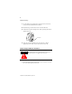
DIN Rail Mounting 1. On the DIN rail, position the expansion block next to your previously-installed base block. 2. Hook the top slot of the block over the DIN rail. 3. Pull down on the locking lever while pressing the block against the rail. f Locking Lever 4. Push up on the locking lever when block is flush against the rail. This secures the block to the rail. Connect an Expansion Block to a Base Block ATTENTION Expansion blocks should not be installed when power is applied to the base. ! 1.
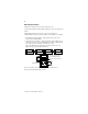
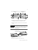
2. Position the expansion block with proper spacing. Base Block Expansion Block 95 mm 3.74 in LDX CompactBlock 1790-16BVOX EXPANSION UNIT 41 mm 1.6 in 95 mm 3.74 in 25 mm 1 in LDX CompactBlock 1790-16BVOX EXPANSION UNIT DC INPUTS 0 7 DC OUTPUTS 0 41 mm 1.6 in 16 INPUTS-DCPOWER 16 INPUTS-DCPOWER 7 0 DC INPUTS 7 0 7 DC OUTPUTS Expansion cover Expansion cover 3. Mount the expansion block using panel or DIN rail mounting, as described in the previous section. 4.
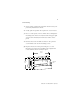
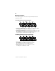
Wire the Expansion Blocks The following figures show the wiring information for the expansion blocks.
1790-T8BV8BX Input/Output Expansion Block Wiring Diagram IN0 IN4 1 IN6 3 2 5 4 11 9 8 IN7 19 18 16 14 OUT1 COM IN3 OUT6 17 15 13 12 10 IN5 OUT4 OUT2 VDC 7 6 IN1 OUT0 COM IN2 OUT3 GND 20 OUT5 OUT7 • Sinking inputs - wire COM (pin 9) to Field Power (-) GND Sourcing inputs - wire COM (pin 9) to Field Power (+) 24Vdc Note: both COM (pins 9 and 10) are internally connected.
1790-T0W8X Relay Output Expansion Block Wiring Diagram VDC OUT1 OUT0 1 3 5 2 11 9 6 8 NC 17 15 13 12 10 OUT7 OUT6 OUT4 7 4 GND OUT5 OUT3 OUT2 18 16 14 19 20 COM1 COM5 COM3 COM7 COM0 COM2 COM6 COM4 NC • Wire VDC (pin 1) to Field Power (+) 24Vdc Wire GND (pin 2) to Field Power (-) GND 1790-T8A0X AC Input Expansion Block Wiring Diagram VAC IN0 1 IN1 3 5 2 IN4 IN2 VAC 7 4 11 9 6 COM 8 19 18 16 14 COM COM COM IN7 17 15 13 12 10 COM COM IN6 IN5 IN3 20 CO
Troubleshoot with the Indicators Use the I/O status indicators to troubleshoot your expansion blocks: I/O Status Indicators Function: LED Color: Module Illumination: Condition: Outputs Each output: Green None Green Output not energized Output energized Inputs Each Input: Green None Green No valid input Valid input Publication 1790-IN005B-EN-P - April 2003
Digital Expansion Block Specifications The following table contains specifications that are common to all of the expansion blocks in this document. Individual expansion block specifications are detailed after this table.
DeviceNet Specifications Network protocol I/O Slave messaging: - Poll command - Bit Strobe command - Cyclic command - COS command Network length 500 meters maximum @ 125Kbps 100 meters maximum @ 500Kbps Indicators 1 red/green module status 1 red/green network status Number of nodes 64 maximum - rotary switch type node address setting Communication rate 125Kbps, 250Kbps, 500Kbps - auto baud rate selection Isolation Type test 1250Vac rms for 60 seconds between field power and DeviceNet (I/O to lo
Universal DC Input Expansion Block Specifications 1790-T16BVOX Inputs per expansion block 16 points, sinking or sourcing On-state voltage 9.6V dc minimum 24V dc nominal 28.8V dc maximum Off-state voltage 5.0V dc maximum On-state current 8mA maximum per channel @ 28.8V dc Nominal input impedance 4.
Nominal input impedance 4.8KΩ Input signal delay Off to On: 10ms maximum On to Off: 10ms maximum Indicators 8 green status Common type 8 points/2 COM (non-polarity) - 1790D-T8BV8VX 8 points/2 COM (non-polarity) - 1790D-T8BV8BX OUTPUT SPECIFICATIONS Outputs per expansion block 8 points non-isolated, sinking - 1790D-T8BV8VX 8 points non-isolated, sourcing - 1790D-T8BV8BX On-state voltage 10V dc minimum 24V dc nominal 28.8V dc maximum On-state voltage drop 0.
DC Output Expansion Block Specifications 1790-TOV16X and -TOB16X Outputs per expansion block 16 points non-isolated, sinking: 1790D-T0V16X 16 points non-isolated, sourcing: 1790D-T0B16X On-state voltage 10V dc minimum 24V dc nominal 28.8V dc maximum On-state voltage drop 0.5V dc maximum On-state current 1mA minimum per channel Off-state voltage 28.8V dc maximum Off-state leakage 0.5mA maximum Output signal delay Off to On: 0.5ms maximum On to Off: 1.
AC/DC Relay Output Expansion Block Specifications 1790-TOW8X Relay type Form A, normally open Single pole, single throw Output voltage range (load dependent) 5-28V dc @ 2.0A resistive 48V dc @ 0.8A resistive 125V ac @ 2.0A resistive 250V ac @ 2.0A resistive Minimum load 100µA, 100mV dc per point Maximum on-state voltage drop 0.5V @ 2.0A, resistive load, 24V dc Initial Contact Resistance 30mΩ Expected contact life 300K cycles resistive 100K cycles inductive Maximum off-state leakage 1.
AC Input Expansion Block Specifications 1790-T8AOX Inputs per expansion block 8 points non-isolated On-state voltage range 79V ac minimum 110V ac nominal 132V ac maximum Input impedance 18KΩ On-state current 9mA maximum @132V ac Off-state voltage 45V ac maximum Input signal delay 10ms off to on 30ms maximum on to off Indicators 8 green input status Common type 8 points/8COM General Specifications External AC power supply Supply voltage - 110V rms, 60Hz Voltage range - 85-132Vrms, 47-63H
110V AC Output Expansion Block Specifications 1790-T0A8X Outputs per expansion block 8 points non-isolated Load voltage range 15-132Vrms Maximum load current 0.5Arms Minimum load current 10mArms Max off-state leakage current 1.0mArms @ 100Vrms 60Hz Max on-state voltage drop 1.
The following information applies when operating this equipment in hazardous locations: Informations sur l’utilisation de cet équipement en environnements dangereux : Products marked “CL I, DIV 2, GP A, B, C, D” are suitable for use in Class I Division 2 Groups A, B, C, D, Hazardous Locations and nonhazardous locations only. Each product is supplied with markings on the rating nameplate indicating the hazardous location temperature code.
This product has been tested at an Open Device Vendors Association, Inc. (ODVA) authorized independent test laboratory and found to comply with ODVA Conformance Test. Please contact the ODVA website (http://www.odva.org) for listing of products tested by ODVA independent test labs for further details. CompactBlock LDX and RSNetWorx are trademarks of Rockwell Automation.
Publication 1790-IN005B-EN-P - April 2003 Supersedes Publication 1790-IN005A-EN-P - April 2001 PN 957782-57 © 2003 Rockwell Automation.