
Instruction Manual

18
Publication 1790-IN010B-EN-P - April 2003
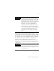
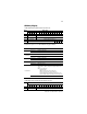
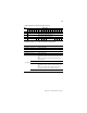
Word/Bit Descriptions for 1790P-TN0C2 Analog Output Module
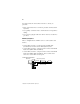
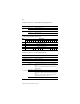
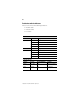
1790P-T4R0 RTD Module Input Data File
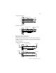
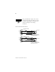
Word/Bit Descriptions for 1790P-T4R0 RTD Module
Word Decimal Bit Description
Write Word
0
Bits 00-11 Channel 0 output data
Bits 12-15 Not used: Set to 0
Write Word
1
Bits 00-11 Channel 1 output data
Bits 12-15 Not used: Set to 0
Word Bit Position
1514131211109876543210
0 RTD Input Data Channel 0
1 RTD Input Data Channel 1
2 RTD Input Data Channel 2
3 RTD Input Data Channel 3
4 Not Used S11 S10 S9 S8 Not Used S3 S2 S1 S0
Word Decimal Bit Description
Read Word 0 Bits 00-15 Channel 0 input data
Read Word 1 Bits 00-15 Channel 1 input data
Read Word 2 Bits 00-15 Channel 2 input data
Read Word 3 Bits 00-15 Channel 3 input data
Read Word 4
Bits 00-03 Underrange for individual channels - Bit 00 corresponds to
input channel 0, bit 01 corresponds to input channel 1 and
so on.
When set (1) the input signal is below the input channel’s
minimum range.
Bits 04-07 Not used: Set to 0
Bits 08-11 Overrange for individual channels - Bit 08 corresponds to
input channel 0, bit 09 corresponds to input channel 1 and
so on.
When set (1) the input signal is above the input channel’s
maximum range, or open RTD is detected.
Bits 12-15 Not used: Set to 0