
Instruction Manual

15
Publication 1790-IN010B-EN-P - April 2003
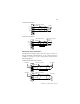
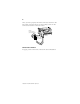
Connect the PROFIBUS DP Terminal Connector
Follow these procedures when connecting the PROFIBUS DP
terminal connector to the base block.
The required PROFIBUS female 9-pin D-sub connector is not
supplied with the base block; you must purchase it separately.
Before you connect the female 9-pin D-sub connector to the
base block, make sure it is wired correctly, as shown in the
following table.
If you connect or disconnect the PROFIBUS
cable with power applied to this module or any
device on the network, an electrical arc can
occur. This could cause an explosion in
hazardous location installations. Be sure that
power is removed or the area is nonhazardous
before proceeding.
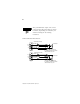
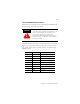
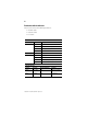
Pin Number: Name: Description:
1 shield Shield, Protective Ground
2 M24V Minus 24V Output Voltage
3 RxD/TxD-P Receive/Transmit-Data-P
4CNTR-P Control-p
5 DGND Data Ground
6VP Voltage-Plus
7 P24V Plus 24V Output Voltage
8 RxD/TxD-N Receive/Transmit-Data-N
9CNTR-N Control-N
WARNING
!