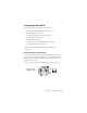
Installation Instructions PROFIBUS DP Analog, RTD and Thermocouple Base Terminal Block CompactBlock LDX I/O (Cat. Nos. 1790P-TN4C0, -TN0C2, -T4R0, -T4T0) What This Document Describes This document describes how to install your PROFIBUS DP CompactBlock LDX I/O.
Important User Information Because of the variety of uses for the products described in this publication, those responsible for the application and use of these products must satisfy themselves that all necessary steps have been taken to assure that each application and use meets all performance and safety requirements, including any applicable laws, regulations, codes and standards.
WARNING ! ATTENTION Identifies information about practices or circumstances that can cause an explosion in a hazardous environment, which may lead to personal injury or death, property damage, or economic loss. Identifies information about practices or circumstances that can lead to personal injury or death, property damage, or economic loss. ! IMPORTANT Identifies information that is critical for successful application and understanding of the product.
Environment and Enclosure This equipment is intended for use in a Pollution Degree 2 industrial environment, in overvoltage Category II applications (as defined in IEC publication 60664-1), at altitudes up to 2000 meters without derating. This equipment is considered Group 1, Class A industrial equipment according to IEC/CISPR Publication 11.
Installing CompactBlock LDX I/O Follow these steps to install the base block: 1. Set the station address on the base block. 2. Mount the base block. 3. Mount the optional expansion blocks. 4. Wire the terminal blocks. 5. Connect field wiring. 6. Wire and connect the PROFIBUS connector. 7. Connect power to the block. These steps are explained in detail in the following procedures. Set the Station Address on the Base Block To set the station address, adjust the switches on the front of the base block.
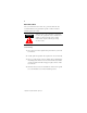
Mount the Base Block You can mount the base block to a panel or DIN rail. We recommend that you ground the panel or DIN rail before mounting the base block. WARNING ! When used in a Class I, Division 2, hazardous location, this equipment must be mounted in a suitable enclosure with the proper wiring method that complies with the governing electrical codes. Panel Mounting 1. Place the base block against the panel where you want to mount it. 2. Gently pull and position the expansion cover to the left.
5. Replace the base block on the panel and place a screw through each of the two mounting holes. Tighten the screws until the base block is firmly in place. 109.5 mm 4.3 in Expansion Cover 42.5 mm 1.7 in DIN Rail Mounting 1. Hook the top slot of the base block over the DIN Rail. 2. Pull down on the locking lever while pressing the base block against the rail. f Locking Lever 3. When the base block is flush against the rail, push up on the locking lever to secure the base block to the rail.
Mount the Optional Expansion Blocks The analog base blocks can accommodate a maximum of two discrete expansion blocks. The RTD and thermocouple base blocks do not support any expansion blocks. IMPORTANT Mount the expansion block by connecting it to a previously-installed CompactBlock LDX I/O base or expansion block.
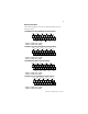
Wire the Terminal Block The following figures show the wiring information for the terminal blocks.
Connect Field Wiring System Wiring Guidelines Follow these guidelines when wiring your system: • Use shielded, twisted pair wire to ensure proper operation and high immunity to electrical noise. • To limit noise, locate RTD and resistance device signal wires as far away as possible from power lines, load lines and other sources of electrical noise, such as hard-contact switches, relays and AC motor drives.
IMPORTANT The RTD block requires three wires to compensate for lead resistance error. We recommend that you do not use 2-wire RTDs if long cable runs are required, as it reduces the accuracy of the system. However, if a 2-wire configuration is required, reduce the effect of the lead wire resistance by using a lower-gauge wire for the cable (for example, use AWG #16 instead of AWG #24). The block’s terminal strip accepts AWG #14 gauge wire.
To ensure that the lead values match as closely as possible: • Keep lead resistance as small as possible and less than 25 ohms. • Use quality cable that has a small tolerance impedance rating. • Use a heavy-gauge lead wire which has less resistance per foot. RTD Wiring Configurations Three configurations of RTDs can be connected to the blocks: • 2-wire RTD, which is composed of an RTD EXC (excitation) lead wire and a RTN (return) wire.
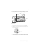
3-Wire RTD Configuration Cable Shield (to Ground) RTD EXC CH0_A RTD EXC Sense Sense CH0_B Return Return COM 4-Wire RTD Configuration Leave this sensor wire open Cable Shield (to Ground) CH0_A CH0_B COM RTD EXC RTD EXC Sense Sense Return Return Wiring Resistance Devices (Potentiometers) Potentiometer wiring requires the same type of cable as that for the RTD.
The potentiometer wiper arm can be connected to either the EXC or return terminal, depending on whether you want increasing or decreasing resistance.
Connect the PROFIBUS DP Terminal Connector Follow these procedures when connecting the PROFIBUS DP terminal connector to the base block. WARNING ! If you connect or disconnect the PROFIBUS cable with power applied to this module or any device on the network, an electrical arc can occur. This could cause an explosion in hazardous location installations. Be sure that power is removed or the area is nonhazardous before proceeding.
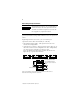
Once you have properly wired the connector, attach it to the base block as shown below. Use the locking screws on the connector to fasten it to the base block. Module Power Connector (underneath module) Green - GND Black - COM Red - +24Vdc PROFIBUS Connector Connect Power to the Block To apply power to the block, refer to the above illustration.
I/O Memory Mapping 1790P-TN4C0 Analog Input Module Input Data File Word Bit Position 15 14 13 12 11 10 9 8 7 6 5 4 3 0 Not Used Analog Input Data Channel 0 1 Not Used Analog Input Data Channel 1 2 Not Used Analog Input Data Channel 2 3 Not Used 2 1 0 S2 S1 S0 Analog Input Data Channel 3 4 Not Used S3 Word/Bit Descriptions for 1790P-TN4C0 Analog Input Module Word Read Word 0 Read Word 1 Read Word 2 Read Word 3 Decimal Bit Description Bits 00-11 Channel 0 input data
Word/Bit Descriptions for 1790P-TN0C2 Analog Output Module Word Decimal Bit Description Write Word 0 Bits 00-11 Channel 0 output data Bits 12-15 Not used: Set to 0 Write Word 1 Bits 00-11 Channel 1 output data Bits 12-15 Not used: Set to 0 1790P-T4R0 RTD Module Input Data File Word Bit Position 15 14 13 12 11 10 9 8 7 6 0 RTD Input Data Channel 0 1 RTD Input Data Channel 1 2 RTD Input Data Channel 2 3 5 4 3 2 1 0 S3 S2 S1 S0 RTD Input Data Channel 3 4 Not Used
1790P-T4T0 Thermocouple Module Input Data File Word Bit Position 15 14 13 12 11 10 9 8 7 6 5 0 Thermocouple Input Data Channel 0 1 Thermocouple Input Data Channel 1 2 Thermocouple Input Data Channel 2 3 4 3 2 1 0 S3 S2 S1 S0 Thermocouple Input Data Channel 3 4 Not Used S11 S10 S9 S8 Not Used Word/Bit Descriptions for 1790P-T4T0 Thermocouple Module Word Decimal Bit Description Read Word 0 Bits 00-15 Channel 0 input data Read Word 1 Bits 00-15 Channel 1 input da
Troubleshoot with the Indicators The base block has the following indicators: • module status • network status • I/O status Mod/Net Status Indicator LED Indicator: Status: Description: Module Status Solid Red Unrecoverable fault in base block Flashing Red Unrecoverable fault in expansion unit Solid Green Normal operation - OK Off No power Status: Description: LED Indicator: Network Status Solid Red Unrecoverable communication fault Flashing Red Recoverable communication fault Solid
RTD and Thermocouple Blocks - I/O Channel LED Status Indicator Status: Description: Flashing Green/Red Power up Off Off line Red On line and no field power Red PROFIBUS connection and no field power Flashing Red Field power and open wire Green Field power and valid input Flashing Red Input over range Flashing Red Input under range Flashing Red Recoverable fault I/O Channel LED Status Indicator 1790D-TN4C0 1790D-TN0C2 Status: Description: Status: Description: Flashing Green/ Red
PROFIBUS DP Digital Base Terminal Block Specifications The following table contains specifications that are common to all of the analog, RTD and Thermocouple base blocks in this document. Individual base block specifications are detailed after this table.
PROFIBUS DP Specifications Network Protocol PROFIBUS-DP (EN50170) • Communication of the slave with a Class 1 master • Communication of the slave with a Class 2 master Redundancy Not supported Repeater Control Signal RS485 signal Implementation Type DPC31 Freeze Mode Supported Sync Mode Supported Auto Baud Rate Supported Fail Safe Mode Supported1 Station Type Slave FMS Support Not supported Indicators 1 red/green module status 1 red/green network status Number of nodes 100 maximum -
4-Channel Analog Current Input Block Specifications 1790P-TN4C0 Inputs per module 4 channel single-ended, non-isolated Input Current (software configurable) 4-20mA (default) 0-20mA Resolution 12 bits-unipolar 1/4096 maximum 3.90µA/bit (4-20mA) 4.88µA/bit (0-20mA) Converted Data Binary data 0000 to 0fff (max scale) Conversion Time 10ms/channel Overall accuracy 0.
2 Channel Analog Current Output Block Specifications 1790P-TN0C2 Outputs per module 2 channel single-ended, non-isolated Output Current 0-20mA Resolution 12 bits 1/4096 maximum 4.88µA/bit Converted Data Binary data 0000 to 0fff (max scale) Conversion Time 2ms/channel Overall accuracy 0.
4-Channel Input RTD Base Block Specifications 1790P-T4R0 Inputs per module Input Range Sensors Supported Resolution Data Format Module Scan Time Overall accuracy Settable Notch Filter Open Wire Detection Excitation Current Input Impedance 4 channel, RTD/Resistance Input 1-625 Sensor Type Degree Counts Resolution Resistance 100mΩ 1 to 625Ω 10 to 6250 100mΩ Resistance 10mΩ 1 to 327Ω 100 to 10mΩ 32700 100ohm Pt/α =0.00385 -200 to -2000 to 0.1°C +850°C +8500 200ohm Pt/α =0.00385 -200 to -2000 to 0.
General Specifications PROFIBUS Power Supply voltage - 24V dc nominal Voltage range - 19.2-28.8V dc Power dissipation - 1.2W maximum @ 28.8V dc Field Power Supply Voltage - 24Vdc nominal Voltage Range - 21.6-26.4V dc (+10%) Power Dissipation - 1.5W maximum @26.
4-Channel Input Thermocouple Base Block Specifications 1790P-T4T0 Inputs per module Input Range Sensors Supported Resolution Data Format Module Scan Time Overall accuracy Settable Notch Filter Open Wire Detection Cold Junction Compensation Range Input Impedance General Specifications PROFIBUS Power 4 channel, Thermocouple/mV Input +76.50mV Sensor Type Range Scaling Voltage 10V -76.50 to +76.
l The following information applies when operating this equipment in hazardous locations: Informations sur l’utilisation de cet équipement en environnements dangereux : Products marked “CL I, DIV 2, GP A, B, C, D” are suitable for use in Class I Division 2 Groups A, B, C, D, Hazardous Locations and nonhazardous locations only. Each product is supplied with markings on the rating nameplate indicating the hazardous location temperature code.
lImportant: Input and output wiring must be in accordance with Class 1, Division 2 wiring methods and in accordance with the authority having jurisdiction. Allen-Bradley and CompactBlock LDX are trademarks of Rockwell Automation. PROFIBUS DP is a trademark of PROFIBUS Trade Organization.
Publication 1790-IN010B-EN-P - April 2003
Publication 1790-IN010B-EN-P - April 2003 Supersedes Publication 1790-IN010A-EN-P - January 2002 PN 957657-65 © 2003 Rockwell Automation.