NI-FBUS Configurator 1788-FFCT User Manual
Important User Information Because of the variety of uses for the products described in this publication, those responsible for the application and use of these products must satisfy themselves that all necessary steps have been taken to assure that each application and use meets all performance and safety requirements, including any applicable laws, regulations, codes and standards.
Rockwell Automation Support Rockwell Automation offers support services worldwide, with over 75 sales/support offices, 512 authorized distributors, and 260 authorized systems integrators located throughout the United States alone, plus Rockwell Automation representatives in every major country in the world.
Table of Contents Important User Information . . . . . . . . . . . . . . . . . Rockwell Automation Support . . . . . . . . . . . . . . . Local Product Support . . . . . . . . . . . . . . . . . . Technical Product Assistance . . . . . . . . . . . . . Your Questions or Comments on this Manual . Preface . . . . . . . . . . . . . . . . . . . . . . . . . . . . . . . . . . . . . . . . iii iv iv iv iv Conventions Used in This Manual . . . . . . . . . . . . . . . . . . . . ix Related Documentation . . .
vi Tabs of the Block Window. . . . . . . . . Editing Block Parameters . . . . . . . . . . Updating Block Parameter Values. . . . Using Menus and Methods . . . . . . . . . . . Configuring Alarms . . . . . . . . . . . . . . . . . Configuring Trends . . . . . . . . . . . . . . . . . Viewing and Editing a Schedule. . . . . . . . Schedule Window Toolbar . . . . . . . . . Changing the Link Active Schedule. . . Multiple Loop Representation . . . . . . . Setting Network Parameters. . . . . . . . . . .
Preface This manual gives an overview of fieldbus, describes the NI-FBUS Configurator, and explains how to use the NI-FBUS Configurator. The NI-FBUS Configurator is intended for use with Microsoft Windows NT. This manual assumes that you are already familiar with Windows NT. Conventions Used in This Manual This manual uses the following conventions: <> Angle brackets enclose the name of a key on the keyboard—for example, .
Preface x Publication 1788-UM052B-EN-P - April 2002
Chapter 1 Fieldbus Overview This chapter introduces fieldbus and the parts of a fieldbus network. This chapter contains fieldbus information that will help you use the NI-FBUS Configurator and solve problems with the configuration of your fieldbus system. Refer to the Glossary for more explanation of fieldbus terms and concepts. If you already have a basic knowledge of fieldbus concepts, or if you want to start using the NI-FBUS Configurator immediately, skip to Chapter 3, NI-FBUS Configurator Overview.
1-2 Fieldbus Overview Links A FOUNDATION Fieldbus network is made up of devices connected by a serial bus. This serial bus is called a link. Links can be separated by special devices called bridges. Figure 1.1 shows a link in a fieldbus network. Figure 1.
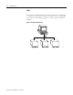
Fieldbus Overview 1-3 Devices There are three types of devices on a fieldbus network: the link master, basic devices, and bridges. • Link master –A link master device controls the communications traffic on a link. A link master prevents multiple devices from communicating data at the same time. A link master can be a Distributed Control System (DCS) or any other device, such as a valve or a pressure transducer.
1-4 Fieldbus Overview Blocks and Parameters Functions that can be performed by a device are represented as function blocks. Function blocks contain algorithms and algorithm-controlling parameters.
Fieldbus Overview 1-5 Device Description Files The vendor supplied Device Description (DD) files describe the function and transducer blocks contained in a device. A DD file includes symbolic information (such as names and help strings) and functional information (such as menus and methods that you can use with the device). DDs are used with the NI-FBUS Configurator to configure a device.
1-6 Fieldbus Overview Loops A loop or control loop is a group of function blocks connected by linkages executing at a configured rate. Each block executes at the configured rate and data moves across the linkages between the blocks at the configured rate. Figure 1.5 shows an example of a control loop. Figure 1.5 Control Loop Loop = 1 sec 43274 Multiple Loops It is possible to have multiple loops running at different rates on a link. Figure 1.6 shows an example of multiple loops. Figure 1.
Fieldbus Overview 1-7 Even if loops are running at different rates, they can send each other data through linkages. Figure 1.7 shows an example of a linkage between two loops. All loops on a link run within one macrocycle. A macrocycle is the least common multiple of all the loop times on a given link. For example, the macrocycle in Figure 1.7 is 1 second. Figure 1.
1-8 Fieldbus Overview Schedules A schedule of data traffic allows communication to be deterministic, meaning that data is transferred between a given set of devices at the same time during each loop. The schedule can be divided into two parts: a function block schedule that determines when a block executes, and a publishing schedule that determines when data parameters are published over the fieldbus.
Chapter 2 Configuring a Fieldbus System This chapter contains brief instructions on how to configure a typical fieldbus system. Refer to Chapter, Fieldbus Overview, or the Glossary for an explanation of fieldbus terms or concepts. Refer to Chapter 3, NI-FBUS Configurator Overview, for information about a specific control or window in the NI-FBUS Configurator.
2-2 Configuring a Fieldbus System 3. Set addresses and tags. • Each device has a physical device tag and a fieldbus network address. You must assign a unique tag to each device. Each address must be unique within a fieldbus segment. • Each device has function blocks that perform control functions, such as AI, AO, DI, DO, PID, and so on. Devices also have transducer blocks that perform I/O with sensors and actuators. You must assign a unique tag to function and transducer blocks.
Configuring a Fieldbus System 2-3 6. Configure alarms. Using the NI-FBUS Configurator, you can configure fieldbus devices to generate alarms. Thus, you do not need an HMI to generate alarms. To configure alarms, identify the function blocks that generate alarms and the hosts that receive the alarms. You must also configure the alarm limits and priorities. For instructions on how to configure alarms, refer to the Configuring Alarms section on page 4-25. 7. Configure trends.
2-4 Configuring a Fieldbus System 10. Set network parameters. For communication and scheduling to function properly, you must configure the fieldbus communication-specific network parameters. An example of a network parameter is identifying the primary time master and the primary Link Active Scheduler (LAS) devices. For instructions on how to set network parameters, refer to the Setting Network Parameters section on page 4-30. 11. Download a configuration.
Chapter 3 NI-FBUS Configurator Overview This chapter introduces the NI-FBUS Configurator, lists some of its main features, and describes the main windows of the application. Introduction to the NI-FBUS Configurator You can use the NI-FBUS Configurator to configure a fieldbus network and keep track of your configuration changes.
3-2 NI-FBUS Configurator Overview NI-FBUS Configurator Windows The NI-FBUS Configurator has three moveable, dockable windows within the Configurator Main window: the Project, Help, and Status windows. Configurator Main Window The Configurator Main window has menus at the top, and contains the windows described in the following sections. Figure 3.1 shows the Project, Help, and Status windows within the Configurator Main window. Figure 3.
NI-FBUS Configurator Overview 3-3 Project Window The Project window, which appears to the left of the Configurator Main window by default, displays the configurable objects of the link connected to the NI-FBUS Configurator. To configure each object, double-click these objects in the Project window; doing so opens the correct interface to use to configure the object. Figure 3.2 shows the Project window. Figure 3.
3-4 NI-FBUS Configurator Overview Each object in the Project window has its own menu that appears on the main taskbar when you select the object. You can also view the menu by right-clicking the object, as shown in Figure 3.3. Figure 3.3 Project Window Pop-Up Menu Conventions The NI-FBUS Configurator uses the following standard user interface conventions: • Double-click an object to open the configuration interface.
NI-FBUS Configurator Overview 3-5 Icons Descriptions of the project icons that appear in the Project window follow: Icon Name Description Link This icon represents the fieldbus segment to which your PC is connected. Double-click this icon to open the Network Parameters window. Log/Notes Double-click this icon to see a summary of all the changes you have made to the project link.
3-6 NI-FBUS Configurator Overview Toolbar The toolbar at the top of the Project window helps you perform basic operations on your project. Figure 3.4 shows the Project window toolbar. Figure 3.4 Project Toolbar Descriptions of the buttons on the Project toolbar follow: Button Name Publication 1788-UM052B-EN-P - April 2002 Description Errors Click this button to validate the project. New Link Click this button to add another link to the project.
NI-FBUS Configurator Overview 3-7 Help Window The Help window, which appears to the right of the Configurator Main window by default, displays help information for the object over which you place your cursor. The text is generated from the NI-FBUS Configurator and Device Description (DD) files. To hide the Help window, select Window ⇒ Help Window. Figure 3.
3-8 NI-FBUS Configurator Overview Download Tab The Download tab shows all the status information for the last configuration download of the bus. The NI-FBUS Configurator retains this information until the next download. The Download tab automatically appears on top when you begin to download your configuration. The status information on the Download tab is also in the Log/Notes window. Errors Tab The Errors tab, shown in Figure 3.
Chapter 4 Using the NI-FBUS Configurator The following sections describe how to use the NI-FBUS Configurator to configure your fieldbus system. Starting the NI-FBUS Configurator Before you use the NI-FBUS Configurator, you must install and configure your software and any fieldbus interfaces, as instructed in your getting started manual. To start the NI-FBUS Configurator, complete the following steps: 1. Select Start ⇒ Programs ⇒ NIFBUS ⇒ NI-FBUS Configurator. The Add Links window opens. 2.
4-2 Using the NI-FBUS Configurator Configuring Online When you start the NI-FBUS Configurator, or when you create a new project, the Add Links window opens. To add new links at any other time, click the Link button in the toolbar. TIP You can edit saved configuration files without connecting to the fieldbus. To open a saved configuration, click Cancel to close the Add Links window that opens. Select File ⇒ Open and browse to your saved configuration files, which have a .fcp extension.
Using the NI-FBUS Configurator 4-3 Figure 4.1 shows the Project window with an example list of fieldbus objects. For more information about the parts of the Project window, refer to the Project Window section on page 3-3. Figure 4.
4-4 Using the NI-FBUS Configurator Importing Device Description Files To use Device Description (DD) files with the NI-FBUS Configurator, you must import the DD files: 1. Select Start ⇒ Programs ⇒ NI-FBUS ⇒ Interface Config to run the Interface Configuration utility. 2. Click DD Info. The DD Info window opens. 3. Type the base directory for your DD files in the first field. 4. If necessary, click Browse to select your standard text dictionary. 5. Click Import DD. The Import DD window opens. 6.
Using the NI-FBUS Configurator Setting Device or Block Tags 4-5 Setting a device or block tag may affect how other host machines on an (online) operating network access the device. IMPORTANT The operating control system must not be using the device or function block when you set tags. When you set the device tag, the device loses all linkage and communication configuration information and loses control of the process. To set a tag, complete the following steps: 1.
4-6 Using the NI-FBUS Configurator 7. After you successfully set the tag, use the Block window to change the block from OOS mode to a desired mode. Setting Device Addresses IMPORTANT The operating control system must not be using the device when you set the address. When you set the address, the device deletes all communication information. Complete the following steps to set the device address: 1. In the Project window, select the desired device. 2.
Using the NI-FBUS Configurator 4-7 3. Select Set Address from the pop-up menu that opens. The Set Address window opens. 4. In the New Address field, select the desired address from the drop-down list. 5. Select the Set to OOS Mode checkbox. Doing so sets the block to OOS mode, which prevents the device from operating in its current control system. 6. Click Set. The NI-FBUS Configurator sets the device resource block to out of service (OOS) mode before setting the new address.
4-8 Using the NI-FBUS Configurator Resetting a Device to Factory Defaults You can clear a device so that it is reset to a state appropriate for shipping. To do so, right-click on the device name in the Project window and select Set to Factory Defaults from the popup menu that opens. The NI-FBUS Configurator clears the device and function block tags, along with the device address. In addition, it clears all communication information in the device.
Using the NI-FBUS Configurator 4-9 Descriptions of the items on this toolbar follow: Table 4.1 Function Block Application Toolbar Descriptions Toolbar Item Name Description FBAP Name This field shows the name of the function block application. Loop Execution Time This field shows the default execution rate of the process loop. Stale Limit This field shows the number of consecutive duplicate values that a function block accepts before it labels the input data as stale (old data).
4-10 Using the NI-FBUS Configurator Function Blocks As stated in the Blocks and Parameters section of Chapter 1, function blocks contain an algorithm and several parameters to control a process. The input and output parameters of this function block are displayed on the block, as in Figure 4.4. Figure 4.4 Input and Output Parameters on a Function Block The pointers on the outside of the parameters show the direction of the data flow.
Using the NI-FBUS Configurator 4-11 You can also add function blocks as follows: 1. Right-click on the background of the Function Block Application Editor or click the Block button. 2. Select the device from the menu that opens, then select the block you want to place on the screen from the menu of function blocks. TIP You can use a function block on a fieldbus network only once.
4-12 Using the NI-FBUS Configurator Connecting Blocks To send data from one block to another, you must connect the blocks through wiring. You can wire blocks manually or use a template. Wiring Blocks Manually To wire blocks manually, complete the following steps: 1. Click the Wiring tool on the Function Block Application Editor toolbar. 2. Click the input or output you want to connect. 3.
Using the NI-FBUS Configurator 4-13 You can also drag devices from the Project window into the Function Block Application Editor to configure alarms and trends, as described in the Configuring Alarms and Configuring Trends sections on pages 4-25 and 4-26, respectively. Using Pre-Wired Templates Templates are predefined, pre-wired control loops that you can drag into the Function Block Application Editor to use as a model for your function block application.
4-14 Using the NI-FBUS Configurator Figure 4.7 shows an example of a template. Figure 4.7 Example Template If template blocks are grayed out, as shown on the left in Figure 4.7, you have not assigned a function block to the template block. To assign a function block to the template block, complete the following steps: 1. Double-click the template block to view all the blocks that match this block type in your project. You can also right-click the block and select Replace from the popup menu that opens.
Using the NI-FBUS Configurator 4-15 Defining Multiple Loops A loop is a group of connected function blocks that execute at a specified rate. You can define many loops in one Function Block Application Editor window. Figure 4.8 shows an example of two separate loops running at the same rate. Figure 4.
4-16 Using the NI-FBUS Configurator Defining Multiple Loops Running at Different Rates The loop execution time shown on the Function Block Application Editor toolbar is the default execution time for all function blocks on the window not isolated in a loop structure. For example, the AI and PID blocks in Figure 4.9 execute at a rate of once every second, but the AI-PID-AO loop can be set to execute at another time by modifying the time at the top of the shaded area. Figure 4.
Using the NI-FBUS Configurator 4-17 You can use the loop structure shown in Figure 4.10 to isolate a group of function blocks to run at a different execution rate than the rate on the Function Block Application Editor toolbar. Figure 4.10 Loop Structure To create a loop structure, complete the following steps: 1. Click the Loop tool on the Function Block Application Editor toolbar. 2.
4-18 Using the NI-FBUS Configurator Changing the Block Execution Order To change the execution order of the blocks, complete the following steps: 1. In the Function Block Application Editor, click the Change Execution Order button. Numbers appear on the blocks, indicating their current order. 2. Click on the blocks in the order that you want them to execute. 3. When you are done, click on the background of the Function Block Application Editor window or select another tool.
Using the NI-FBUS Configurator Viewing and Editing Function Block Parameters 4-19 Each function block in your application has a Block window that you can use to change block parameters and other settings. When you read or write data on a block, the Status window shows the status of the transactions. To open the Block window for a block, do one of the following: • Double-click on the name of the function block in the Project window.
4-20 Using the NI-FBUS Configurator Block Window Icons As shown in Figure 4.11, an icon to the left of each parameter name color-codes and symbolically represents the class of the parameter. Table 4.2 describes the classes of the parameter. Table 4.2 Block Window Icons Shape Color Description Circle Alarms—Green Others—Black Represents contained parameters. Contained parameters cannot be linked to other parameters; they are contained in the block.
Using the NI-FBUS Configurator 4-21 Descriptions of the icons on this toolbar follow: Toolbar Item Name Description Device Tag This field shows the function block tag. To change the block tag, click the field. Write Changes Click this button to write only changed parameters to the block on the device, including changed block tags. Write All Click this button to write all parameters, including changed block tags, to the block on the device.
4-22 Using the NI-FBUS Configurator Adding Tabs To add a tab to the Block window, complete the following steps: 1. Click the Add or Delete Custom Tab button in the Block window toolbar. The Add & Delete Custom Tabs window opens. 2. Click the section where you want to add the tab. 3. Click Add and type the name of the new tab in the edit control that opens. 4. Click OK to generate the new tab. Removing Tabs To remove a tab from the Block window, complete the following steps: 1.
Using the NI-FBUS Configurator 4-23 Editing Block Parameters The Block window displays the parameters in the order that they appear in the block. Parameters with a plus sign beside them are records or arrays (structures) that contain more than one entry. To expand the record or array, click the plus sign, or to collapse the structure, click the minus sign. To edit a block parameter value, complete the following steps: 1.
4-24 Using the NI-FBUS Configurator Updating Block Parameter Values You can update block parameter values manually or automatically, as described below: Manually To update each block parameter value manually, select the parameter and click the Read Selected button on the Block window toolbar. To update all of the block parameter values, click the Read All button. Automatically To update the block parameter values automatically, complete these steps: 1.
Using the NI-FBUS Configurator Using Menus and Methods 4-25 If you double-click a function block in the Project window and the block has menus and methods associated with it, a menu bar opens above the Block window toolbar and the Methods tab opens in the Block window. To invoke a method, select it from the menu bar. Figure 4.13 Methods pull-down menu Configuring Alarms To configure a device, such as a PC, to receive alarms generated by function blocks complete the following steps: 1.
4-26 Using the NI-FBUS Configurator 3. Double-click the function block that you want to generate the alarm. The Block window opens. 4. Select the Alarms tab to view or change alarm information, such as the high and low limits of an alarm condition, alarm priorities, and so on. Configuring Trends You can configure a device, such as a PC, to receive trends from fieldbus devices. To configure trends, complete the following steps: 1.
Using the NI-FBUS Configurator Viewing and Editing a Schedule 4-27 The NI-FBUS Configurator automatically determines the execution order and timing of the schedule based on your control strategy, network and device factors, and on the loop execution rate you choose. The NI-FBUS Configurator also automatically optimizes the schedule. Double-click the Schedule icon in the Project window to view or edit the link active schedule.
4-28 Using the NI-FBUS Configurator Schedule Window Toolbar Figure 4.15 shows the toolbar for the Schedule window. Figure 4.15 Schedule Toolbar Descriptions of the icons on the Schedule window toolbar follow: Toolbar Item Name Description Primary LAS This field displays the name of the device that is the primary LAS for the system. Scale This field displays the time and divisions on the timing diagram. Errors Click this button to validate the schedule.
Using the NI-FBUS Configurator 4-29 Multiple Loop Representation Figure 4.16 shows how the NI-FBUS Configurator displays multiple loops in the Schedule window. Figure 4.16 Multiple Loops in a Schedule The loops are separated by white dividers. Select the checkbox by the loop time shown above the colored bars to lock the loop and prevent you and the NI-FBUS Configurator from changing the schedule until you uncheck the box.
4-30 Using the NI-FBUS Configurator Setting Network Parameters To change network parameters such as the Link Active Scheduler (LAS) and primary time master, double-click the Network Parameters icon in the Project window, or click the Link Masters button in the Download Configuration window. The Network Parameters window opens. This window lists all devices capable of being link master. Every device you select in this window receives the Link Active Schedule when you download your configuration.
Using the NI-FBUS Configurator Downloading a Configuration 4-31 When you download a configuration, the NI-FBUS Configurator configures the following items: • • • • • • Function block linkages between devices Function block schedule Alarms configuration Trends configuration Static parameters Communication schedule for the LAS To download your configuration, complete the following steps: 1. Click the Download button in the Project window toolbar or select Configure ⇒ Download Configuration.
4-32 Using the NI-FBUS Configurator 6. (Optional) If you want the NI-FBUS Configurator to switch function blocks in the configuration to OOS mode and back to the desired mode automatically, select the Automatic Mode Handling checkbox. If you do not select this checkbox, you are responsible for changing the modes during the download process. 7. To download your fieldbus configuration changes to the network, click Download.
Using the NI-FBUS Configurator Verifying a Configuration 4-33 This section describes two ways to verify your configuration: a quick verification and a comparison of the configuration to a saved project. Quick Verification You can perform a quick check to verify that the parameters on the bus match those in the project. To verify the configuration of a link, device, or function block, complete the following steps: 1. Right-click the object to display the popup menu and select Verify Configuration.
4-34 Using the NI-FBUS Configurator Comparing Two Configurations You can upload your current bus configuration and compare it against a saved project. To do so, click the Verify and Diff button in the Project window toolbar. You can also select Configure ⇒ Verify and Diff Configuration. The NI-FBUS Configurator uploads device parameter values, function block schedules, trend and alarm connections, and function block application linkages, and compares them with the saved configuration.
Using the NI-FBUS Configurator Viewing and Editing a Log 4-35 The Log/Notes window keeps track of the last downloaded configuration status output. The Log/Notes window shows the same output as the Download Log tab of the Status window plus the time and date of the last change and previous downloads of the current project. To open the Log/Notes window, double-click the Log/Notes icon in the Project window. Figure 4.18 shows the Log/Notes window. Figure 4.
4-36 Using the NI-FBUS Configurator 3. In the Correct Device field, select the new device from the drop-down list to replace the Missing Device. 4. After you select the desired devices, click Done. The NI-FBUS Configurator replaces the Missing Device with the Correct Device. When you download your changes, the new configuration, including linkages, tags, and parameter values, is written to the Correct Device.
Using the NI-FBUS Configurator Changing the Software Key 4-37 The NI-FBUS Configurator software license has a default number of links that you can configure. If you purchase additional licenses to access more than the default number of links, contact National Instruments to obtain a new software key. After you obtain a new key, complete the following steps to change the key: 1. Select View ⇒ Preferences and select the Links tab. 2. Click Show About Dialog. The About window opens. 3.
4-38 Using the NI-FBUS Configurator Printing You can print your configured project in the form of text, graphical diagrams, and text explanations of the diagrams. To print your project, select File ⇒ Print. The Print window opens. Under What to Print, you can choose to print the Entire Configuration or only Specific Configuration Items.
Appendix A Error Messages and Warnings This appendix lists error messages you might receive while using the NI-FBUS Configurator and describes the error messages. Error Messages If you receive an error message while using the NI-FBUS Configurator, refer to this section for a description of the error and possible solutions. Error Possible Solution NIF_ALARM_ACKNOWLEDGED The alarm has already been acknowledged. NIF_BAD_ARGUMENT The value you gave is not of the correct data type.
A-2 Error Messages and Warnings Error Possible Solution NIF_SERVER_NOT_RESPONDING Either the NI-FBUS server has not been started, or the server, in its current state, cannot respond to the request. NIF_SM_NOT_OPERATIONAL The device is present, but cannot respond because it is at a default address. NIF_SYMBOL_FILE_NOT_FOUND NI-FBUS could not find the symbol file. NIF_TIMEOUT The device containing the object is present but did not respond within the timeout period.
Error Messages and Warnings A-3 Error Possible Solution NIFCONF_ERR_MACROCYCLE_CONFLICT This macrocycle conflicts with a previously defined macrocycle time for a device in this loop. Devices can only schedule one macrocycle time. The best solution is to increase the macrocycle time of the loop that contains the other block(s) for this device. NIFCONF_ERR_MACROCYCLE_NOT_GOOD_MULTIPLE This macrocycle is a bad choice in comparison to the other macrocycles.
A-4 Error Messages and Warnings Error Possible Solution NIFCONF_ERR_TOO_MANY_LAS_SCHEDULE_ENTRIES The number of LAS schedule entries exceeds the number of available entries in the LAS device. Choose integer multiple macrocycle values and reduce the number of data links that go between devices to correct this problem. NIFCONF_ERR_TYPE_INFO_UNAVAILABLE The NI-FBUS Configurator cannot read the type information for the object.
Appendix B Troubleshooting and Common Questions This appendix describes how to troubleshoot problems and answers some common questions. To determine how to solve a problem, refer to Table 2.1. Table 2.1 Troubleshooting Problems Problem Possible Causes Solution A function block alternates between IMAN and AUTO modes. The status of the input parameter is Bad::No comm. The function block and communication schedules do not have enough time between them. Refer to Mode Transition on page B-4.
B-2 Troubleshooting and Common Questions Table 2.1 Troubleshooting Problems (Continued) Problem Possible Causes Solution A device does not publish the data you configured it to transmit. The function execution time parameter in the function block does not accurately represent the execution time. Refer to the Transmission Problems section on page B-4. Your interface(s) does not appear in the Add Links dialog box. You may need to upgrade your software key to support the additional links.
Troubleshooting and Common Questions B-3 Device Problems If you receive a status of Bad:Device Failure, set the RESTART parameter in the Block window to Processor or Default. If the problem persists, replace the device. If a device does not accept a permanent address, you must set the device tag. For instructions on setting the tag, refer to the Setting Device or Block Tags on page 4-5. If the device already has a tag, the T3 network parameter might not be the right length.
B-4 Troubleshooting and Common Questions Transmission Problems If a device does not transmit alarms or trends, you have not configured them yet. For instructions on how to configure alarms and trends, refer to the Configuring Alarms and Configuring Trends sections on pages 4-25 and 4-26, respectively. If a device does not publish the data you configured it to transmit, complete these steps: 1. Edit the schedule to add more time to the communication schedule.
Troubleshooting and Common Questions B-5 If the PID does not transition to AUTO mode, complete these steps: 1. Make sure that the AI and AO are publishing. 2. Make sure that the LAS executes the communication schedule. If not, select Configure ⇒ Download Configuration to download the configuration. For information about downloading the configuration, refer to the Downloading a Configuration section on page 4-31. 3. Make sure the target mode of the downstream block is set to CAS.
B-6 Troubleshooting and Common Questions Common Questions How can I speed up the control? If the control is slow, the macrocycle time might be too long. To speed up the control, edit the function block schedule and decrease the macrocycle time. For more information about editing the schedule, refer to the Viewing and Editing a Schedule section on page 4-27.
Glossary We use these abbreviations, acronmys, and initialisms throughout the document. 1 Term Definition AI Analog Input AO Analog Output basic device a device that can communicate on the fieldbus, but cannot become the LAS BG Bias Gain block A logical software unit that makes up one named copy of a block and the associated parameters its block type specifies. The values of the parameters persist from one invocation of the block to the next.
G-2 Publication 1788-UM052B-EN-P - April 2002 Term Definition function block A named block consisting of one or more input, output, and contained parameters. The block performs some control function as its algorithm. Function blocks are the core components you control a system with. The Fieldbus Foundation defines standard sets of function blocks. There are ten function blocks for the most basic control and I/O functions.
Index A Add & Delete Custom Tabs dialog box (figure) 4-22 Add Links (figure) 4-1 dialog box missing from interface B-6 Added Function Blocks 4-11 (figure) 4-11 Adding function blocks 4-10 allways then iv and iv B Basic device 1-3 Block window (figure) 4-6, 4-19, 4-23, 4-26 icons 4-20 (table) 4-20 toolbar 4-20 (figure) 4-20 Blocks identifying 1-5 Blocks and Parameters 1-4 Bridge 1-3 C Changing the block execution order 4-18 the link active schedule 4-28 Common Questions B-6 Configurator Main Window 3-2 (fi
I-2 I Icons 3-5 Identifying blocks 1-5 devices 1-3 Import DD dialog box (figure) 4-4 Importing Device Description Files 4-4 Input and Output Parameters on a Function Block (figure) 4-10 Input and Output Parameters on a Function Block 4-10 Input parameters 1-4 Interface missing B-2, B-6 Introduction to Fieldbus 1-1 to the NI-FBUS Configurator 3-1 L Link master 1-3 Linkage between function blocks (figure) 1-5 between two loops (figure) 1-7 Linkages 1-5 Links 1-2 Log/Notes Window (figure) 4-35 Loop Structure
I-3 Q Quick Verification 4-33 R Reading and Writing Errors B-5 Related Documentation vii Removing tabs 4-22 Replace Devices (figure) 4-35 Resetting a Device to Factory Defaults 4-8 S Schedule Toolbar (figure) 4-28 Schedule Window (figure) 4-27 toolbar 4-28 Schedules 1-8 Set Address dialog box (figure) 4-7 Setting device addresses 4-6 Device or Block Tags 4-5 Speed control B-6 Starting the NI-FBUS Configurator 4-1 State Icons 3-5 descriptions of 3-5 Status Tab 3-7 Status Window 3-7 Subscribed parameter 1
I-4 Publication 1788-UM052B-EN-P - April 2002
How Are We Doing? Your comments on our technical publications will help us serve you better in the future. Thank you for taking the time to provide us feedback. You can complete this form and mail it back to us, visit us online at www.ab.com/manuals, or email us at RADocumentComments@ra.rockwell.com Pub. Title/Type NI-FBUS Configurator User Manual Cat. No. 1788-FFCT Pub. No. 1788-UM052B-EN-P Pub. Date April 2002 Part No. 957678-81 Please complete the sections below.
PLEASE FASTEN HERE (DO NOT STAPLE) PLEASE FOLD HERE NO POSTAGE NECESSARY IF MAILED IN THE UNITED STATES BUSINESS REPLY MAIL FIRST-CLASS MAIL PERMIT NO.
Publication 1788-UM052B-EN-P - April 2002 9 Supersedes Publication 1788-UM052A-EN-P - January 1999 PN 957678-81 Copyright © 2002 Rockwell Automation. All rights reserved. Printed in the U.S.A.