
User Manual Owner manual


58 Rockwell Automation Publication 1788-UM058B-EN-P - September 2014
Appendix A Linking Device Display Status
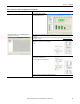
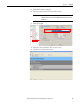
The lower portion of the main page shows the communication quality to each
field device represented as a percentage of data packets sent compared to data
packets received for each field device index (see Tab l e 8
).
Table 8 - Field Device Communication Quality
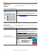
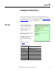
PA Master Page
The next page that is accessed by
the Page button is the PA Master
page.
Bus A/B: Displays the bus
voltages and currents.
Tem p er at ur e : Displays the
internal temperature of the linking
device.
External Pwr: Displays the power
supply voltage.
PA Node: Displays the node
address of the linking device.
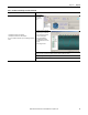
Bus A/B Enabled: PA Bus A and/or PA Bus B is enabled for communication.
Bus A/B Tripped: PA Bus A and/or PA Bus B has tripped indicating that there
was an over-current on either port.
Bus A/B Term: The linking device is configured to terminate PA Bus A and/or
PA Bus B.
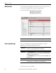
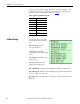
Display Communication Quality
>>> 95+
>> 80+
>70+
X60+
XX 50+
XXX Below 50
??? Unknown