User Manual EtherNet/IP and ControlNet to PROFIBUS PA Linking Devices Catalog Numbers 1788-EN2PAR, 1788-CN2PAR
Important User Information Read this document and the documents listed in the additional resources section about installation, configuration, and operation of this equipment before you install, configure, operate, or maintain this product. Users are required to familiarize themselves with installation and wiring instructions in addition to requirements of all applicable codes, laws, and standards.
Table of Contents Preface Important User Information . . . . . . . . . . . . . . . . . . . . . . . . . . . . . . . . . . . . . . . . 2 Introduction. . . . . . . . . . . . . . . . . . . . . . . . . . . . . . . . . . . . . . . . . . . . . . . . . . . . . . . 7 About the Linking Devices . . . . . . . . . . . . . . . . . . . . . . . . . . . . . . . . . . . . . . 7 Network Diagrams . . . . . . . . . . . . . . . . . . . . . . . . . . . . . . . . . . . . . . . . . . . . . . . . .
Table of Contents Configure PV with Multiple Formats . . . . . . . . . . . . . . . . . . . . . . . . . . Valve Positioner Configuration. . . . . . . . . . . . . . . . . . . . . . . . . . . . . . . . . . . . PROFIBUS PA Redundancy Setup . . . . . . . . . . . . . . . . . . . . . . . . . . . . . . . . Hardware . . . . . . . . . . . . . . . . . . . . . . . . . . . . . . . . . . . . . . . . . . . . . . . . . . . . Software . . . . . . . . . . . . . . . . . . . . . . . . . . . . . . . . . . . . . . . . . . . . .
Table of Contents Glossary Index Rockwell Automation Publication XXXX-X.X.
Table of Contents 6 Rockwell Automation Publication XXXX-X.X.
Preface Introduction This user manual describes the installation and operation of the 1788-EN2PAR and 1788-CN2PAR linking devices. About the Linking Devices The 1788-EN2PAR linking device provides a fast and integrated solution for adding PROFIBUS PA (process automation) field devices to any Logix platform. This linking device provides a direct link between PROFIBUS PA and EtherNet/IP networks with no intermediate PROFIBUS DP (decentralized peripherals) layer required.
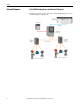
Preface Network Diagrams 1788-EN2PAR Linking Device and EtherNet/IP Network This diagram shows an example of how the 1788-EN2PAR linking device can be used with an EtherNet/IP network.
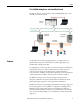
Preface 1788-CN2PAR Linking Device and ControlNet Network The diagram shows an example of how a 1788-CN2PAR linking device can be used with a ControlNet network. ControlLogix Controller 1788-CN2PAR Linking Device 1788-CN2PAR Linking Device 1788-FBJB4R Junction Boxes Features The AOP provides an intuitive graphical interface to configure devices. A predefined data structure for each field device provides eight input process variables (PVs) and eight output PVs.
Preface Built-in power conditioners and protection help to minimize installation space requirements. The PA segment is divided between two physical ports (A and B) with individual protection and a supply of 500 mA per port. See PA Network Connections on page 16. Basic diagnostics of the linking device and field devices is found in the input assemblies. Advanced configuration is accomplished only through the AOP.
Preface Environment and Enclosure ATTENTION: Environment and Enclosure • This equipment is intended for use in a Pollution Degree 2 industrial environment, in overvoltage Category II applications (as defined in IEC 606641), at altitudes up to 2000 m (6562 ft) without derating. • This equipment is not intended for use in residential environments and may not provide adequate protection to radio communication services in such environments. • This equipment is supplied as open-type equipment.
Preface European Hazardous Location Approval The following applies when the product bears the marking. This equipment is intended for use in potentially explosive atmospheres as defined by European Union Directive 94/9/EC and has been found to comply with the Essential Health and Safety Requirements relating to the design and construction of Category 3 equipment intended for use in Zone 2 potentially explosive atmospheres, given in Annex II to this Directive.
Preface North American Hazardous Location Approval The following information applies when operating this equipment in hazardous locations. The following information applies when operating this equipment in hazardous locations: Informations sur l'utilisation de cet équipement en environnements dangereux: Products marked "CL I, DIV 2, GP A, B, C, D" are suitable for use in Class I Division 2 Groups A, B, C, D, Hazardous Locations and nonhazardous locations only.
Preface Additional Resources These documents contain more information about related products from Rockwell Automation. Resource Description FOUNDATION Fieldbus Linking Devices Technical Data, publication 1788-TD001 Provides technical data and specifications for the FOUNDATION Fieldbus linking devices.
Chapter 1 Installation Hardware ATTENTION: Do not wire multiple conductors on any single terminal. Dimensions 80 mm (3.15 in) 136 mm (5.35 in) 152 mm (5.98 in) Power Connection To comply with the CE Low Voltage Directive (LVD), this equipment must be powered from a source compliant with Safety Extra Low Voltage (SELV) or Protected Extra Low Voltage (PELV). To comply with UL restrictions, this equipment must be powered from a source compliant with Class 2 or Limited Voltage/Current.
Chapter 1 Installation We recommend a 24…32V DC power supply for the linking device to operate correctly. No additional power supplies or power conditioners are required. The power supply connection is described here. Tighten DC Power connections to a torque of 0.22…0.25Nm (2…2.2 lb-in). IMPORTANT Do not use extra power supplies or power conditioners with the 1788-EN2PAR and 1788-CN2PAR linking devices. PA Network Connections The PA network must be connected via the PA terminal on the linking device.
Installation Chapter 1 The PA network connections are described here.
Chapter 1 Installation ControlNet and EtherNet/IP Connections Two BNC (Bayonet Neill-Concelman) connectors on the base of the 1788-CN2PAR linking device provide connections for single or dual ControlNet media. The dual port EtherNet/IP switch provides connections for multiple EtherNet/IP topologies, including device level ring (DLR). The EtherNet/IP port can also be used as a connection point in the field to access the Web server or asset management tools. The ControlNet connections are described here.
Installation IMPORTANT Chapter 1 If the shield is not correctly connected, noise from the environment on the PA bus can cause the PA data to be corrupted. Corrupted data can result in a low success rate and device connections being lost. Section 12.8.5 of IEC61158-2 (Physical Layer Specification), indicates that 90% of the full length of the cable must be shielded. See Grounding/Earthing on page 19 for more details for shield connections.
Chapter 1 Installation Cable Path Do not route the PROFIBUS PA cable near any motors or high-voltage/ high-current cables. Motors and high-voltage/high-current cables can generate noise that decreases communication signal quality on the PA cable, which can corrupt PA packets and cause field device timeouts. Cable Lengths Load and voltage drop determine maximum cable length.
Installation Chapter 1 Cable Type and Minimum Requirements Per section 12.8.2 of IEC61158-2 (Physical Layer Specification), the PROFIBUS PA cable must meet the following minimum requirements: • Impedance at 31.25 kHz of 100 Ω ± 20% • Maximum attenuation of 3 dB/km • Conductor cross-sectional area of 0.8mm2 (18 AWG) • Shield coverage of at least 90% • Maximum DC resistance of 24 Ω/km per conductor • Maximum capacitive unbalanced to the shield of 4nF/km Cable Color Coding Per section 12.8.
Chapter 1 Installation Set the Linking Device Network Address This section describes the network address switches. Hardware Switches Location The hardware switches are located under the front cover of the linking device. Use the Page button to toggle between different diagnostics on the display. Set the ControlNet Node Address To set the ControlNet node address of the 1788-CN2PAR linking device, use the hardware switches behind the front cover.
Installation Chapter 1 Set the EtherNet/IP Address The linking device uses an RJ45 connector to connect to an Ethernet network. The linking device ships with BOOTP enabled. To set the IP address of the 1788-EN2PAR linking device, use a BOOTP server or use the hardware switches. IMPORTANT Power down the linking device before changing the Ethernet switch settings. The IP address is set during powerup.
Chapter 1 Installation Ethernet Switch Settings This table describes the Ethernet switch settings. Ethernet Switch Setting Description To set the IP address of the linking device to the 192.168.1.xxx sub net, set the switches to the required last three digits. In this example, the linking device will start up with IP address: 192.168.1.123. To set the IP address of the linking device via a BOOTP server, set the switches to 888 (factory default setting).
Installation Software Installation Chapter 1 You need the AOP for the Studio 5000 Logix Designer application to configure and manage the linking device. The installation of the AOP includes the HSProcessUtility that is used to manage DTMs and GSD service libraries. For the latest compatible software information and to download the AOP, see the Product Compatibility and Download Center at http://www.rockwellautomation.com/rockwellautomation/support/ pcdc.page#/tab2.
Chapter 1 Installation Notes: 26 Rockwell Automation Publication 1788-UM058B-EN-P - September 2014
Chapter 2 Set Up in the Studio 5000 Logix Designer Application Add the 1788-EN2PAR Linking Device to the I/O Tree The 1788-EN2PAR linking device must be added to the I/O tree of the Logix controller. The linking device must be added to an Ethernet bridge module, such as an Allen-Bradley 1756-EN2T or 1756-EN2TR module. Follow these steps to add the linking device to the I/O tree of the Logix controller. This example uses the 1756-EN2T module. 1. Right-click the Ethernet bridge and choose New Module. 2.
Chapter 2 Set Up in the Studio 5000 Logix Designer Application Add the 1788-CN2PAR Linking Device to the I/O Tree The 1788-CN2PAR linking device must be added to the I/O tree of the Logix controller. The linking device must be added to a ControlNet bridge module, such as an Allen-Bradley 1756-CNB or 1756-CNBR module. Follow these steps to add the linking device to the I/O tree of the Logix controller. This example uses the 1756-CNBR module. 1. Right-click the ControlNet bridge and choose New Module. 2.
Set Up in the Studio 5000 Logix Designer Application Configure the Linking Device Chapter 2 After the linking device is added to the I/O tree, you can configure the device properties. 1. Right-click the linking device and choose Properties. 2. Click the Configuration tab to open the configuration page for the linking device. Process Catalog Launches the HSProcessUtility that manages the GSD files and DTMs.
Chapter 2 Set Up in the Studio 5000 Logix Designer Application Download Downloads the configuration to the linking device. The linking device saves the configuration in non-volatile memory. IMPORTANT After the configuration has been downloaded to the linking device, cycle power for the new configuration to take effect. Upload Uploads the configuration from the linking device to the Studio 5000 Logix Designer project.
Set Up in the Studio 5000 Logix Designer Application Configure the PA Master Chapter 2 Topology Mode Choose the correct topology mode for the application. The graphical representation must match the actual topology. See Appendix B for available options. Use this setting to configure redundant linking devices, redundant PA media, and the internal PA segment terminators. PA Node The PA master (linking device) needs a node number to operate on the PA bus. The default is node number 1.
Chapter 2 Set Up in the Studio 5000 Logix Designer Application Configure the Field Devices This section describes how to configure one PV and multiple PVs for a slot. Configure PV with Single Format Each field device can have multiple PVs, each with a different format. In most cases the default configuration correctly configures each PV, but if you add, remove, or change PVs, make sure to change the format if needed. Table 2 shows available PV format options.
Set Up in the Studio 5000 Logix Designer Application Chapter 2 Configure PV with Multiple Formats In some cases (for example, positioner field devices), there are multiple input and output PVs per slot. See Valve Positioner Configuration on page 34 for details. IMPORTANT Select the number of inputs and outputs, and their respective PV formats, as shown in the user manual of the field device. In the input image of the field device, the PV is set per the manual slot configuration.
Chapter 2 Set Up in the Studio 5000 Logix Designer Application Valve Positioner Configuration A valve positioner typically has only one slot that has multiple predefined inputs and outputs. Consult the user manual for the device to verify the definition for each option. One basic option is to configure the valve positioner to receive a setpoint from the ControlLogix controller via the linking device and to return the defined position. Follow these steps for setting the valve positioner. 1.
Set Up in the Studio 5000 Logix Designer Application Chapter 2 4. Configure the input and output formats for the slot configuration. IMPORTANT See the documentation for the valve positioner to verify the correct data format for each option. In this example, the setpoint sent to the valve positioner is a real value with a 1-byte status. The actual position that the valve positioner returns is also a real value with a 1-byte status, with an added 1 byte with status and discrete position. 5.
Chapter 2 Set Up in the Studio 5000 Logix Designer Application PROFIBUS PA Redundancy Setup The linking device provides PROFIBUS PA and Ethernet architectures. This section describes the PROFIBUS PA redundancy options that are available, and highlights the benefits and sets required to implement them. Hardware This section describes the hardware redundancy for media and master devices. Media Redundancy For media redundancy, you can select from dual trunk or ring redundant media architecture.
Set Up in the Studio 5000 Logix Designer Application IMPORTANT Chapter 2 When using ring redundancy, enable the auto-terminate function on the 1788PARJB junction box. See the1788-PARJB Quick Start Guide, publication 1788QS005, for details. Failure to enable the auto-terminate function can cause network termination issues that can cause the network to become unstable. Limitations The linking device can support a maximum of 24 field devices and a maximum current supply of 500 mA per trunk.
Chapter 2 Set Up in the Studio 5000 Logix Designer Application Master and media redundancy can run simultaneously as shown in Figure 5. Figure 5 - MultiMaster and Media Redundancy More junction boxes can be added to the dual trunk. See Appendix B for valid redundancy configurations. IMPORTANT When using dual trunk architecture, use the 1788-PARJB junction box. Limitations A maximum of two linking devices can be added to one network.
Set Up in the Studio 5000 Logix Designer Application Chapter 2 Software IMPORTANT Choose the architecture that is used in the field before downloading the configuration. If the incorrect architecture is chosen, the network will not function correctly. Media Redundancy If the dual trunk redundancy is selected, you can view the PA Bus, and Channel A and Channel B diagnostics (voltage, current, and so on) as shown in Figure 6.
Chapter 2 Set Up in the Studio 5000 Logix Designer Application A short on either bus is indicated in the Studio 5000 Logix Designer application, or in the AOP as shown in Figure 7. Figure 7 - Bus Short/Open Circuit IMPORTANT The linking device can only detect a short/open circuit on either of the trunks that are connected directly to the linking device. If there is a fault between two junction boxes, you will only see the fault by examining the junction boxes in the field.
Set Up in the Studio 5000 Logix Designer Application Chapter 2 MultiMaster Mode When running in redundant master mode (MultiMaster mode), the PA master can be in one of three different states: • Primary Active • Secondary Active • Master Config Mismatch • Master Node Mismatch Primary Active The Primary Active linking device is the primary master that is currently providing communication. Secondary Active The Secondary Active linking device is the secondary master (hot backup).
Chapter 2 Set Up in the Studio 5000 Logix Designer Application Master Config Mismatch The Master Config Mismatch state occurs when the PA master configuration does not match the other PA master on the PA network. IMPORTANT Both masters must have the same master and field device configurations. Master Node Mismatch The Master Node Mismatch state occurs when the primary and secondary masters do not have the same node address.
Set Up in the Studio 5000 Logix Designer Application Redundant PA Code Example Chapter 2 When running in MulitMaster mode, the data appears twice in the Logix controller (once for each PA master). A combination of PA master status, MulitMaster active, and field device connection statuses are used as criteria. The example code in Figure 8 provides an AOI to control the redundant PA.
Chapter 2 Set Up in the Studio 5000 Logix Designer Application Notes: 44 Rockwell Automation Publication 1788-UM058B-EN-P - September 2014
Chapter 3 Logix Assemblies PA Master Input Image Each linking device uses a total of four connections from the Logix controller, regardless of the field device count. Therefore, the input and output image of each linking device is divided into four sections, A through D. Connection A has the data for the linking device and four field devices. Connections B, C, and D have the data of four field devices each. Figure 9 shows the input image of the PA master.
Chapter 3 Logix Assemblies ModuleStatus This word is currently reserved. Connection Status If a field device is online and running (exchanging cyclic data), then the field device index bit in the connection status is set. If the device goes offline, the bit is cleared. Field Device Input Image Each field device displays its PA diagnostics and all available PVs and their status as shown in Figure 10. Figure 10 - Field Device Input Image PANode The node number of the field device on the PA bus.
Logix Assemblies Chapter 3 ParameterFault This bit is set if there is a fault in the parameterization of the field device. ParameterReq This bit is set if the device has not received its parameterization. FreezeMode This bit is set if you enable Freeze mode in the parameterization of the field device and a global control is sent to freeze the device PVs. SyncMode This bit is set if you enable Sync mode in the parameterization of the field device and a global control is sent to synchronize the device PVs.
Chapter 3 Logix Assemblies Field Device Output Image Each field device displays its PA diagnostics and all available PVs and their status as shown in Figure 11. Figure 11 - Field Device Output Image PVInt1…PVInt8 If you are using a field device that requires an output, the data must be updated in the output image of that field device. If a real value must be sent, use the copy function to update the PVInt.
Chapter 4 Diagnostics Linking Device is Offline Use these diagnostic checks to help you identify and fix the problem when the linking device goes offline. Table 3 - Linking Device is Offline Diagnostic Checks Symptom Checks Does the linking device have power, and did it powered up? Verify that the LCD backlight is on and information is displayed on the LCD screen.
Chapter 4 Diagnostics Field Device is Not Detected Use these diagnostic checks to help you identify and fix the problem when a field device is not detected. Table 4 - Field Device is Not Detected Diagnostic Checks Symptom Checks Are the PA node addresses set on the field devices? If you are using the soft address setting, add only one field device at a time and set the node address before adding the next field device.
Diagnostics Chapter 4 Table 4 - Field Device is Not Detected Diagnostic Checks (Continued) Symptom Checks Check the PA bus voltage in the AOP. Check if the PA bus has tripped. The linking device AOP scan reports NO DEVICES FOUND when linking devices are connected. Verify that the cable used in the PA network is in compliance with section 12.8.2 of IEC61158-2 (Physical Layer Specification).
Chapter 4 Diagnostics Use these diagnostic checks to help you identify and fix the problem when the field device is not configured. Field Device is Not Configured Table 5 - Field Device is Not Configured Diagnostic Checks Symptoms Checks The field device is attached but is not producing process variables in the controller. Devices are blue or switch blue/red. This condition usually indicates the configuration is incorrect. Verify that the field device configuration is correct.
Diagnostics Chapter 4 Table 6 - Field Device Faults Diagnostic Checks (Continued) Symptoms Checks Launch the DTM and see if the device has any errors. The field device indicates red in the AOP. The field device indicates Err on LCD of module. No process variable is found in the process variable tag of the field device. Check the scope trace in the AOP: • Is there any noise on the bus? • Is the slew rate ok? The wave must not be triangular.
Chapter 4 Diagnostics Web Interface To view device status and diagnostic information that is stored in the web server, enter the device IP address into a web browser and press Enter. For example, linking device IP address 196.135.145.234 IMPORTANT Device Type Manager If data is not being updated, turn off page caching or try another Web browser. You can use the DTM in the profile with the HSThinFrame, or with an FDT Frame (for example, FactoryTalk AssetCentre).
Diagnostics Chapter 4 1. Click Advanced in the config tree. 2. Choose the DTM revision from the pull-down menu. IMPORTANT If you are presented with multiple DTMs of the same device but with different revisions, select the correct DTM and revision for the specific field device. 3. Click Open DTM. 4. Choose the device information that you want to view. 5. View the selected device information.
Chapter 4 Diagnostics Notes: 56 Rockwell Automation Publication 1788-UM058B-EN-P - September 2014
Appendix A Linking Device Display Status The display of the linking device provides status and diagnostic data in one of three page formats: main page, PA master page, or field device page. Use the Page button behind the front cover to scroll through the pages (see Hardware Switches Location on page 22 for location of the Page button). Main Page The main page is the default display. The linking device returns to this page after 10 seconds. PA Bus A/B: Displays the bus voltages on each port.
Appendix A Linking Device Display Status The lower portion of the main page shows the communication quality to each field device represented as a percentage of data packets sent compared to data packets received for each field device index (see Table 8). Table 8 - Field Device Communication Quality PA Master Page Display Communication Quality >>> 95+ >> 80+ > 70+ X 60+ XX 50+ XXX Below 50 ??? Unknown The next page that is accessed by the Page button is the PA Master page.
Linking Device Display Status Field Device Page Appendix A The next 23 Field Device pages display the status of each of the field device indices. PANode: Displays the PA node address. Ident: Displays the ident (identity) number of the specific field device. Status: Displays the field device status (see Table 9). Table 9 - Field Device Status Descriptions Status Message Description Not Connected The device cannot be seen. Online The device is online but not configured.
Appendix A Linking Device Display Status Notes: 60 Rockwell Automation Publication 1788-UM058B-EN-P - September 2014
Appendix B PA Topology Master Mode 0 Single Master A Bus Only Terminated at the linking device. Master Mode 1 Single Master A Bus Only Not terminated at the linking device. Master Mode 2 Single Master B Bus Only Terminated at the linking device.
Appendix B PA Topology Master Mode 3 Single Master B Bus Only Not terminated at the linking device. Master Mode 4 Single Master Dual Bus Terminated at the linking device. Master Mode 5 Single Master Dual Bus Not terminated at the linking device. Master Mode 6 Single Master Split Bus Terminated at the linking device.
PA Topology Master Mode 7 Appendix B Single Master Split Bus Not terminated at the linking device. Master Mode 8 Single Master Ring Bus Master Mode 9 MultiMaster A Bus Only Terminated at the linking devices. Master Mode 10 MultiMaster A Bus Only Shared termination at the linking devices.
Appendix B PA Topology Master Mode 11 MultiMaster A Bus Only Not terminated at the linking devices. Master Mode 12 MultiMaster B Bus Only Terminated at the linking devices. Master Mode 13 MultiMaster B Bus Only Shared termination at the linking devices. Master Mode 14 MultiMaster B Bus Only Not terminated at the linking devices.
PA Topology Master Mode 15 Appendix B MultiMaster Dual Bus Terminated at the linking devices. Master Mode 16 MultiMaster Dual Bus Shared termination at the linking devices.
Appendix B PA Topology Notes: 66 Rockwell Automation Publication 1788-UM058B-EN-P - September 2014
Glossary The following terms and abbreviations are used throughout this manual. For definitions of terms not listed here, refer to the Allen-Bradley Industrial Automation Glossary, publication AG-7.1. 1788-CN2PAR linking device Provides a gateway between ControlNet and a PROFIBUS PA network. 1788-EN2PAR linking device Provides a gateway between EtherNet/IP and a PROFIBUS PA network. 1788-PARJB junction box Provides fault-tolerant connections for a PA network.
Glossary DO Abbreviation for discrete output; signal is generated by the host system and transmitted to a field device. DTM Acronym for Device Type Manager; used to connect to the field device and configure the parameters. Ethernet Physical and data link layer defined by IEEE 802 standards used by EtherNet/IP. EtherNet/IP An open, industrial networking standard that supports both real-time I/O messaging and message exchange.
Glossary ring bus A network where signals are transmitted from one station and replayed through each subsequent station in the network. Signal can travel in either direction of the ring so it creates network redundancy; if the ring breaks in one place the nodes can still communicate. Studio 5000 Logix Designer Software that provides a programming environment for sequential, process, drive, and motion control programming.
Glossary Notes: 70 Rockwell Automation Publication 1788-UM058B-EN-P - September 2014
Index Numerics 1788-PARJB junction box 36, 37, 38, 40 A AOP version 25 auto-terminate function, junction box 37 C cable length, maximum 20 cable path, route to avoid noise 20 communication signal attenuated 21 slewed 21 unreadable 21 communication signal quality 20 ControlNet connections 18 node address 22 node address switches 24 corrupted PA packets 20 current consumption example 19 D default display 57 dimensions 15 display, linking device 57 dual trunk redundancy 39 E earth ground 18 Ethernet switch
Index M main page display CNet MAC 57 IP 57 not owned 57 PA bus A/B 57 status descriptions bus A tripped 57 bus B tripped 57 new device found 57 ok 57 redundancy err 57 redundancy ok 57 safe mode 57 STS (status) 57 STS status descriptions 57 maximum cable length 20 MultiMaster mode config mismatch 42 N network address switches 22 network connection, H1 16 network diagram ControlNet network 9 EtherNet/IP network 8 node address, ControlNet 22, 24 noise, avoiding 20 P PA master configuration class 2 MPPF 31
Index T termination locations 21, 61 terminator impedance 21 V valve positioner 34 Rockwell Automation Publication XXXX-X.X.
Index Notes: 74 Rockwell Automation Publication XXXX-X.X.
Rockwell Automation Support Rockwell Automation provides technical information on the Web to assist you in using its products. At http://www.rockwellautomation.com/support you can find technical and application notes, sample code, and links to software service packs. You can also visit our Support Center at https://rockwellautomation.custhelp.com/ for software updates, support chats and forums, technical information, FAQs, and to sign up for product notification updates.