Installation Instructions Ethernet-to-DeviceNet Linking Device Catalog Number 1788-EN2DN This publication tells you how to install the 1788-EN2DN Ethernet-to-DeviceNet linking device and use RSNetWorx™ for DeviceNet software to configure it.
Ethernet-to-DeviceNet Linking Device Important User Information Solid-state equipment has operational characteristics differing from those of electromechanical equipment. Safety Guidelines for the Application, Installation and Maintenance of Solid State Controls (publication SGI-1.1 available from your local Rockwell Automation™ sales office or online at http://www.rockwellautomation.
Ethernet-to-DeviceNet Linking Device 3 North American Hazardous Location Approval The following information applies when operating this equipment in hazardous locations. Informations sur l’utilisation de cet équipement en environnements dangereux. Products marked “CL I, DIV 2, GP A, B, C, D” are suitable for use in Class I Division 2 Groups A, B, C, D, Hazardous Locations and nonhazardous locations only.
Ethernet-to-DeviceNet Linking Device European Hazardous Location Approval The following applies when the product bears the Ex Marking. This equipment is intended for use in potentially explosive atmospheres as defined by European Union Directive 94/9/EC and has been found to comply with the Essential Health and Safety Requirements relating to the design and construction of Category 3 equipment intended for use in Zone 2 potentially explosive atmospheres, given in Annex II to this Directive.
Ethernet-to-DeviceNet Linking Device 5 Environment and Enclosure ATTENTION: This equipment is intended for use in a Pollution Degree 2 industrial environment, in overvoltage Category II applications (as defined in IEC 60664-1), at altitudes up to 2000 m (6562 ft) without derating. This equipment is considered Group 1, Class A industrial equipment according to IEC/CISPR 11.
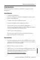
Ethernet-to-DeviceNet Linking Device About the Linking Device The 1788-EN2DN Ethernet-to-DeviceNet linking device lets you seamlessly connect your information- or control-level networks with your device-level network. The linking device provides full DeviceNet master functionality, so you can connect up to 63 DeviceNet slave devices to an Ethernet TCP/IP interface that supports the EtherNet/IP network and an HTTP web server.
Ethernet-to-DeviceNet Linking Device 7 System Requirements The following hardware and software components are required to use the linking device.
Ethernet-to-DeviceNet Linking Device Optional Software RSLogix™ 5000 software, version 13 or later. Installing and Configuring the Linking Device WARNING: If you connect or disconnect the communication cable with power applied to this module or any device on the network, an electrical arc can occur. This could cause an explosion in hazardous location installations. If you connect or disconnect wiring while the field-side power is on, an electrical arc can occur.
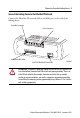
Ethernet-to-DeviceNet Linking Device 9 Connect the Linking Device to the EtherNet/IP Network Connect the EtherNet/IP network cable to the RJ45 port on the end of the linking device. DeviceNet Connection Power Connection Configuration DIP Switch RJ45 Port (EtherNet/IP Connection) 31480-M ATTENTION: This product is grounded through the DIN rail to chassis ground. Use zinc plated yellow-chromate steel DIN rail to assure proper grounding.
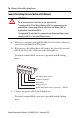
Ethernet-to-DeviceNet Linking Device Connect the Linking Device to the DeviceNet Network ATTENTION: Do not wire more than 2 conductors on any single terminal. To comply with the CE Low Voltage Directive (LVD), this equipment must be powered from a source compliant with Safety Extra Low Voltage (SELV) or Protected Extra Low Voltage (PELV). To comply with UL restrictions, this equipment must be powered from a source compliant with Class 2 or Limited Voltage/Current. 1.
Ethernet-to-DeviceNet Linking Device 11 .. 24V DC common 24V DC + TIP Two 120 ohm termination resistors (supplied with the linking device) may be required for proper network termination at each end of the trunk line. See the DeviceNet Specification (available from the Open DeviceNet Vendors Association at http://www.odva.org) for specific rules on DeviceNet connections and termination. 4. Apply power to the linking device and DeviceNet network. IMPORTANT The linking device defaults to Autobaud.
Ethernet-to-DeviceNet Linking Device Configure the Linking Device IP Address Several methods may be used to set the IP Address. These methods include the following: • IP address configuration DIP switch • DHCP protocol • Web page • RSLogix 5000 software, version 13 or later), and 1788-EN2DN Linking Device, revision 2.x or later Setting the IP Address with the Configuration DIP Switch A configuration DIP switch on the end of the linking device lets you set the IP address.
Ethernet-to-DeviceNet Linking Device 13 The switch represents the binary value of the last byte in the 4-byte IP address. In this case it is n. If n = 0, the linking device obtains its IP address from the software configuration (DHCP or web page). IP address 192.168.1.n Subnet mask 255.255.255.0 Gateway address 0.0.0.0 (No gateway set) Setting the IP Address By Using DHCP/BootP TIP The use of DHCP is the default configuration for the linking device as shipped.
Ethernet-to-DeviceNet Linking Device 1. Click New. You see the Properties dialog box. 2. On the Properties dialog box, enter the appropriate values into the following fields. • Ethernet address (MAC ID) [from the linking device product ID label] • IP address • Subnet Mask • Gateway (IP address) 3. Click OK.
Ethernet-to-DeviceNet Linking Device 15 The following figure shows a flowchart describing how the IP configuration is determined when the linking device is powered up. Start Valid Configuration in Flash Memory? No Yes DIP Switch = 0 Yes No Request config from DHCP/ BOOTP Server. Timeout 30 secs Use received configuration Yes Yes DHCP Config Received? DHCP Enabled? IP = 192 168.1.n Sub = 255.255.255.
Ethernet-to-DeviceNet Linking Device Setting the IP Address Using By Using the Web Page The EtherNet/IP address can also be configured using the IP Configuration web page on the linking device, as shown in the following figure. The IP address can be set with the web page only if the linking device already has a valid IP address. Typically, you can do this by using the DIP switch to force the linking device to use a temporary IP address after you cycle power.
Ethernet-to-DeviceNet Linking Device 17 4. Leave the password field blank. 5. Click OK. You see the IP Configuration dialog box.
Ethernet-to-DeviceNet Linking Device 6. Enter the following values into the IP Configuration dialog box. In this field Enter IP Address Any valid value. See your system administrator for a valid IP address. Subnet Mask Gateway IP Address Any valid value. DHCP enabled 7. Click Submit Values. 8. Follow the on-dialog box prompts. 9. Click the Reset Module button to reset the linking device. Register the Driver in RSLinx Software 1. In RSLinx software, choose Communications>Configure Driver. 2.
Ethernet-to-DeviceNet Linking Device 19 (Optional) Register the EDS file in RSNetWorx Software RSNetWorx for DeviceNet software requires an electronic data sheet (EDS) to recognize a device and its capabilities. If you do not already have a registered EDS file for the device, you can download an EDS file from http://www.rockwellautomation.com/support/downloads.html.
Ethernet-to-DeviceNet Linking Device 4. In the left pane, click DeviceNet, DeviceNet. 5. When asked to upload from the network, click OK to perform a single pass browse.
Ethernet-to-DeviceNet Linking Device 21 Set the DeviceNet MAC ID and Communication Rate 1. In RSNetWorx for DeviceNet software, choose Tools>Node Commissioning. You see the Node Commissioning dialog box. 2. On the Node Commissioning dialog box, click Browse. You see the Device Selection dialog box.
Ethernet-to-DeviceNet Linking Device 3. In the left pane, click the + next to the RSLinx driver for the 1788-EN2DN linking device. 4. In the left pane of the dialog box, click the + next to the IP address for the 1788-EN2DN linking device. 5. In the left pane, click the + next to the DeviceNet network. You see the 1788-EN2DN linking device in the left pane. 6. Click on the 1788-EN2DN linking device in the left pane. It appears in the right pane. 7. Click OK. 8.
Ethernet-to-DeviceNet Linking Device 23 9. Enter the desired MAC address or data rate, then click Apply. 10. Click Close. IMPORTANT The linking device will automatically reset if a new MAC ID is entered. If only the communication rate is changed you must cycle power to the linking device before the new communication rate will take effect. When the MAC ID is changed, the linking device’s I/O configuration is cleared. 11. Restart RSNetworx for DeviceNet software and go online.
Ethernet-to-DeviceNet Linking Device (Optional) Disable Autobaud If you do not want the linking device to automatically determine the network communication rate, disable Autobaud. By default, the linking device has Autobaud enabled. 1. In RSNetWorx for DeviceNet software, highlight the linking device by clicking on its icon. 2. From the pull-down menu, choose Device>Class Instance Editor. 3. If a warning text box appears, click Yes. You see the Class Instance Editor dialog box. 4.
Ethernet-to-DeviceNet Linking Device 25 In this field Select Object Address Class Instance Attribute 3 1 64h Data Sent to Device 00 to enable Autobaud 01 to disable Autobaud Transmit Data Size Byte IMPORTANT Make sure the Values in Decimal checkbox is not checked. 5. Click Execute.
Ethernet-to-DeviceNet Linking Device You should see a message in the Data received from device field indicating that the execution was completed. IMPORTANT Changes to the autobaud option configuration do not take effect until you cycle power to the linking device. You may also have to cycle power to the slave devices. If the linking device is the only master on the DeviceNet network, do not enable autobaud. Automatic communication detection requires traffic on the network.
Ethernet-to-DeviceNet Linking Device 27 (Optional) Configure DeviceNet I/O IMPORTANT Steps 8 and 9 are required only if the linking device is used as an I/O scanner. The linking device can function as a gateway/bridge, even if no I/O is configured. I/O Mapping The DeviceNet I/O configuration defines the format of the Input and Output tables, or the mapping of DeviceNet slaves’ I/O data to the I/O tables.
Ethernet-to-DeviceNet Linking Device 1. In RSNetWorx for DeviceNet, go online by choosing Network>Online. 2. Select Network>Single Pass Browse. Wait for browsing to complete. 3. Select Network>Upload from Network. Wait for the device information to be uploaded from the network. 4. Double-click the linking device icon to bring up the Module Description dialog box. Several tabs appear on the top of the dialog box. 5. Click the Scanlist tab. 6. In the informational text box that appears, click Upload.
Ethernet-to-DeviceNet Linking Device 29 8. Select the I/O devices on the left side of the dialog box and click > to move it to the right side of the dialog box. 9. Select the Input tab. The Input mapping dialog box is displayed. The top portion of this dialog box gives a list of the devices in the scan list from which the linking device receives input data. The bottom shows the location in the Input table where the data will be placed for each device.
Ethernet-to-DeviceNet Linking Device 10. Select the Output tab. The Output mapping dialog box is displayed. The top portion of this dialog box gives a list of the devices in the scan list to which the linking device will send output data. The bottom shows the location in the Output table where the data will be placed for each device. This shows the format of the Output table of the linking device. This is the format of the output data that will be sent to the linking device from the EtherNet/IP scanner.
Ethernet-to-DeviceNet Linking Device 31 3. From the Revision pull-down menu, choose the controller version. 4. Enter a name for the controller project. 5. Click OK. A project is created. 6. In the left pane, right-click I/O Configuration. 7. Click New Module. 8. In the Select Module Type menu, choose any EtherNet/IP Bridge Module (such as the 1788-ENBT module). 9. Click OK. You see the Module Properties dialog box. 10. In the Slot Number field, enter the slot number in which the device resides. 11.
Ethernet-to-DeviceNet Linking Device 14. In the Select Module Type menu, choose 1788-EN2DN/A 1788 Ethernet to DeviceNet Linking Device. 15. Click OK. 16. On the Select Major Revision dialog box that appears, choose the major revision from the drop-down box. 17. Click OK.
Ethernet-to-DeviceNet Linking Device 33 You see the Module Properties dialog box. 18. In the Name field, enter a module name. 19. Click the IP Address radio button and enter the IP address for which the linking device is configured. 20. Click Next. 21. Enter the Requested Packet Interval (RPI or update rate) in a range from 2…750 ms. If you see errors in this field when you are online, see the table following this illustration.
Ethernet-to-DeviceNet Linking Device RSLogix 5000 Software Error Codes This Error code Means So you should 16#0203 Connection timed out Check IP configuration and Ethernet cabling 16#0204 Connection Request Error: Connect request timed out Check IP configuration and Ethernet cabling 16#0103 Service Request Error: CIP transport class not supported Check for valid RPI range (for example, 2…3200ms) 16#0005 Connection Request Error: Bad class.
Ethernet-to-DeviceNet Linking Device 35 24. Write a user program to use the linking device on the network. TIP Consult Rockwell Automation Technical Support or your Rockwell Automation representative for assistance in writing the program. 25. To view information specific to the RSLogix 5000 tags that pertain to the linking device, do the following: a. In the left pane of the RSLogix 5000 software window, click Controller Tags. In the right pane, you see the 1788-EN2DN linking device controller tags. b.
Ethernet-to-DeviceNet Linking Device Assembly Objects and Connections Three Assembly Object instances are accessible from EtherNet/IP: input, output and status. The input and output assemblies are linked to the input and output tags created in RSLogix 5000 software. The status assembly provides current status information about the linking device. IMPORTANT With a specific 1788-EN2DN profile, I/O tags are mapped without an offset.
Ethernet-to-DeviceNet Linking Device 37 Output Assembly The output assembly contains a 32-bit command register followed by the data in the linking device’s output data table. Output Assembly Format DINT Offset DINTs Size in Description RSLogix 5000 software version 12 example tags RSLogix 5000 software version 13 or later example tags 0 1 Command register EN2DN:O.Data[0] EN2DN:O.Command Register 1 Up to 123 Output data EN2DN:O.Data[1 - 123] EN2DN:O.
Ethernet-to-DeviceNet Linking Device Status Assembly Format Byte Offset Size in Bytes Data Type Name (RSLogix 5000 software version 13 or later) Description 0 4 UDINT Scan Counter The number of DeviceNet I/O scans that have taken place since power was applied to the linking device. 4 8 64-bit Bitstring Device Failure Register Indicates which DeviceNet slaves are faulted. Each bit represents the status of the slave at the corresponding MAC ID.
Ethernet-to-DeviceNet Linking Device 39 Status Assembly Format (cont.) Byte Offset Size in Bytes Data Type 42 1 USINT Name (RSLogix 5000 software version 13 or later) 43 1 USINT Scrolling Device Address and Status 44 20 USINT[20] N/A 64 64 USINT[64] Device Status Description The scrolling address and status fields scroll through the address and status of all DeviceNet slaves that are faulted. This scrolling includes the linking device scanner itself.
Ethernet-to-DeviceNet Linking Device Understanding Status Indicators A group of status indicators on the front panel of the linking device shows the current status of the linking device and the network interfaces, as shown in the following figures. The following tables provide information on status indicator states.
Ethernet-to-DeviceNet Linking Device 41 Status Indicators CIP Link Status Indicator Ethernet Link Status Indicator I/O Status Indicator EtherNet Network Status Indicator DeviceNet Network Status Indicator Module Status Indicator 31441-M I/O Status Indicator TIP If the I/O status indicator is flashing red and green for an extended period of time, count the number of red and green flashes and call Rockwell Automation technical support.
Ethernet-to-DeviceNet Linking Device I/O Status Indicator States Indicator Status Description Flashing green Idle Module is in Idle mode. Solid green Running Module is in Run mode. Solid orange Hardware Initialization The status indicator will be in this state immediately after power is applied. Flashing red/green Error A fault has been detected. Off No I/O No DeviceNet I/O configured.
Ethernet-to-DeviceNet Linking Device 43 Module Status Indicator DeviceNet Module Status Indicator States Indicator Status Description Flashing green Standby or not configured The module has not been configured and is currently using default values. This status indicator state is also used to indicate that the module is in a standby state. This could occur during initialization or DeviceNet autobaud. Solid green Normal Normal operation.
Ethernet-to-DeviceNet Linking Device Ethernet Network Status Indicator States Indicator Status Description Solid red Address conflict The module’s IP address is already in use by another module. Flashing Red Connection time-out One or more of the connections in which this module is the target has timed out. This state is only left if all timed out connections are re-established or if the module is reset. Red,Green alternate flashing Self test A self-test of the module is in progress.
Ethernet-to-DeviceNet Linking Device 45 Idle Nodes The Idle Nodes page indicates which DeviceNet nodes are currently in the Idle state. If a node is Idle, the page will display ‘Idle’ next to the node’s MAC ID. Note that only nodes configured as slaves to the linking device and the linking device itself are updated on this page. Faulted Nodes The Faulted Nodes page indicates which DeviceNet nodes are currently in a faulted state.
Ethernet-to-DeviceNet Linking Device Node Status The Node Status page displays the current status of all DeviceNet nodes that are configured as slaves to the linking device and the linking device itself. The status of each node is displayed next to the node’s MAC ID. Note that only nodes configured as slaves to the linking device and the linking device itself are updated on this page. The page will display the status textually for many of the common status values.
Ethernet-to-DeviceNet Linking Device 47 Node Status Codes (cont.) This status code Means So you should 77 Data size expected by the device does not match scan list entry Reconfigure your module for the correct transmit and receive data sizes. 78 Slave device in scan list table does not exist Add the device to the network, or delete the scan list entry for that device. 79 Module has failed to transmit a message Make sure that your module is connected to a valid network.
Ethernet-to-DeviceNet Linking Device Node Status Codes (cont.) This status code Means So you should 88 The connection choices (such as polled or strobed) between the primary connection and the shared input only connection do not match Reconfigure the shared input only connection's choices to be the same as, or a subset of, the primary connection's choice(s). 89 Slave device initialization using Auto Device Replacement parameters failed Put the slave device into configurable mode.
Ethernet-to-DeviceNet Linking Device 49 IP Configuration The IP Configuration web page is used to change the IP configuration of the linking device. Security Use the Security web page to change the security password. Dimensions 52.7 mm 2 in. 100.2 mm 4.3 in. 10 mm 0.425 in. 63 mm 2.4 in. 68.2 mm 2.69 in.
Ethernet-to-DeviceNet Linking Device DeviceNet Connector Pinouts 1 2 3 4 5 31422-M DeviceNet Pinouts Pin Signal 1 V- 2 CAN_L 3 Shield 4 CAN_H 5 V+ EtherNet/IP RJ45 Connector Pinouts 31423-M EtherNet/IP Pinouts Pin Signal 1 TD+ 2 TD- 3 RD+ 4 Termination 5 Termination Rockwell Automation Publication 1788-IN055C-EN-P - September 2011
Ethernet-to-DeviceNet Linking Device 51 EtherNet/IP Pinouts Pin Signal 6 RD- 7 Termination 8 Termination Specifications Technical Specifications - 1788-EN2DN Attribute 1788-EN2DN Enclosure type rating None (open style) Supply power and current rating DeviceNet network: Operating voltage: 12…30V DC (24 V DC nom) 100 mA at 24V DC, Class 2 Input power Operating Voltage: 12…30V DC (24V DC nom) 300 mA at 24V DC, Class 2 Isolation voltage 50V (continuous), basic insulation type Torque 0.5… 0.
Ethernet-to-DeviceNet Linking Device Technical Specifications - 1788-EN2DN Attribute 1788-EN2DN Wire size DeviceNet connections: See appropriate system-level installation manual Ethernet network connections: RJ45 connector according to IEC 60603-7, 2 or 4 pair Category 5e minimum cable according to TIA 568-B.1 or Category 5 cable according to ISO/IEC 24702 DC Power connections: 0.2… 3.3 mm2 (24…12 AWG) solid or stranded copper wire rated at 75 °C (167 °F), or greater, 1.2 mm (3/64 in.
Ethernet-to-DeviceNet Linking Device 53 Environmental Specifications - 1788-EN2DN Attribute 1788-EN2DN Relative humidity • IEC 60068-2-30 (Test Db, Unpackaged Damp Heat) 5…95% noncondensing Vibration • IEC 60068-2-6 (Test Fc, Operating) 5 g @ 10…500 Hz Shock, operating • IEC 60068-2-27 (Test Ea, Unpackaged Shock) 30 g Shock, nonoperating • IEC 60068-2-27 (Test Ea, Unpackaged Shock) 50 g ESD immunity • IEC 61000-4-2 6 kV contact discharges 8 kV air discharges Radiated RF immunity • IEC 61000-4-3
Ethernet-to-DeviceNet Linking Device Certifications - 1788-EN2DN Certification (when product is marked)(1) 1788-EN2DN c-UL-us UL Listed for Class I, Division 2 Group A,B,C,D Hazardous Locations, certified for U.S. and Canada. See UL File E194810. CE European Union 2004/108/EC EMC Directive, compliant with: • EN 61326-1; Meas./Control/Lab.
Ethernet-to-DeviceNet Linking Device 55 Additional Resources These documents contain additional information concerning related products from Rockwell Automation. Resource Description EtherNet/IP Modules in Logix5000 Control Systems User Manual, publication ENET-UM001 Provides information about how to use EtherNet/IP modules with various Logix5000 controllers.
Rockwell Automation Support Rockwell Automation provides technical information on the Web to assist you in using its products. At http://www.rockwellautomation.com/support/, you can find technical manuals, a knowledge base of FAQs, technical and application notes, sample code and links to software service packs, and a MySupport feature that you can customize to make the best use of these tools.