Installation Instructions DeviceNet Daughtercard Catalog Number 1788-DNBO This document describes how to install and configure the DeviceNet™ 1788-DNBO daughtercard. The daughtercard is a DeviceNet scanner that provides DeviceNet monitoring, configuration, and I/O scan capabilities.
DeviceNet Daughtercard Important User Information Because of the variety of uses for the products described in this publication, those responsible for the application and use of these products must satisfy themselves that all necessary steps have been taken to assure that each application and use meets all performance and safety requirements, including any applicable laws, regulations, codes and standards.
DeviceNet Daughtercard ATTENTION ! 3 Environment and Enclosure This equipment is intended for use in a Pollution Degree 2 industrial environment, in overvoltage Category II applications (as defined in IEC publication 60664-1), at altitudes up to 2000 meters without derating. This equipment is considered Group 1, Class A industrial equipment according to IEC/CISPR Publication 11.
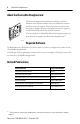
DeviceNet Daughtercard About the DeviceNet Daughtercard The network daughtercard architecture defines a common hardware and software interface that several different network interface cards will support. This lets products that have been designed to support the network daughtercard option support several different Rockwell Automation networks. You can install the 1788-DNBO DeviceNet daughtercard in any host device that supports the DeviceNet daughtercard.
DeviceNet Daughtercard 5 Preventing Electrostatic Discharge ATTENTION ! Preventing Electrostatic Discharge This equipment is sensitive to electrostatic discharge, which can cause internal damage and affect normal operation. Follow these guidelines when you handle this equipment: • • • • • • Touch a grounded object to discharge potential static. Wear an approved grounding wriststrap. Do not touch connectors or pins on component boards. Do not touch circuit components inside the equipment.
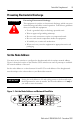
DeviceNet Daughtercard Set the Network Baud Rate You must set one switch to configure the network baud rate. Figure 1 shows the location of the switch. The switch is read on power-up. Set the switch to a value between 0 and 2, according to this table: Switch Setting Baud Rate 0 125Kb 1 250Kb 2 500Kb Install the Daughtercard Due to wide variation in available host devices, we cannot provide specific installation instructions in this document.
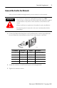
DeviceNet Daughtercard 7 Connect the Card to the Network After you have installed the daughtercard, you can connect it to the network. If you insert or remove the card while host power is on OR if you connect or disconnect the DeviceNet cable with power applied to this module or any device on the network, an electrical arc can occur. WARNING ! Either could cause an explosion in hazardous location installations. Be sure that power is removed or the area is nonhazardous before proceeding. 1.
DeviceNet Daughtercard Daughtercard Performance Due to wide variation in available host devices, we cannot provide specific performance capabilities in this document. For information concerning host/daughtercard performance characteristics, refer to the user manual for the particular host device. Interpret the LED Status Indicators The three status indicators on the daughtercard provide information about the network, the daughtercard, and its connections.
DeviceNet Daughtercard 9 Network Status (NS) Indicator This bi-color (green/red) LED indicates the status of the communication link. Condition Status Indicates off not powered, not online Device is not online. The device has not completed the Dup_MAC_ID test yet. The device may not be powered; look at the Module Status LED. flashing green1 online, not connected Device is online, but has no connections in the established state.
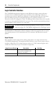
DeviceNet Daughtercard Logix Controller Interface The 1788-DNBO daughtercard supports several different size input, output, and status structures when communicating with Logix controllers, such as FlexLogix. These I/O structures were created to reduce the complexity of connecting DeviceNet I/O and status data with ladder programs. The daughtercard creates all 3 structures whether or not DeviceNet nodes are configured or online.
DeviceNet Daughtercard 11 Module Command Register Bit Definitions The bits of the Module Command Register are defined as follows: Bit Name Description 0 Run 1 = run mode 0 = idle mode 1 Fault 1 = fault network 2 DisableNetwork 1 = disable network 3 HaltScanner 1 = halt module (The daughtercard ceases all operation.) 4 Reset 1 = reset module (Put back to 0 to resume operation.
DeviceNet Daughtercard Module Status Register Bit Definitions The bits of the Module Status Register are defined as follows: Bit Name Description 0 Run 1 = in run mode. 0 = in idle mode. 1 Fault 1 = network is faulted. 2 DisableNetwork 1 = network is disabled. 3 DeviceFailure 1 = device failure exists (examine the status structure for causes). 4 AutoverifyFailure 1 = at least one device has failed to be initialized by the daughtercard. 5 CommFailure 1 = communication failure exists.
DeviceNet Daughtercard 13 The status structure consists of these data elements: Status Structure Element Description Data Type ScanCounter counter incremented each I/O scan 32-bit DeviceFailureRegister device failed bit table; 1 = failed 64-bit AutoverifyFailureRegister device I/O size does not match scanner’s internal table; 1 = mismatch 64-bit DeviceIdleRegister device is idle bit table; 1 = idle 64-bit ActiveNodeRegister node online bit table; 1 = online 64-bit StatusDisplay ASCII re
DeviceNet Daughtercard Hazardous Location Information The following information applies when operating this equipment in hazardous locations: Informations sur l’utilisation de cet équipement en environnements dangereux : Products marked “CL I, DIV 2, GP A, B, C, D” are suitable for use in Class I Division 2 Groups A, B, C, D, Hazardous Locations and nonhazardous locations only. Each product is supplied with markings on the rating nameplate indicating the hazardous location temperature code.
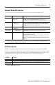
DeviceNet Daughtercard 15 Specifications Characteristic Value Power Requirements Host 5V dc @ 260mA(1) DeviceNet 24V dc @ 20mA Class 2 Power Consumption 5 V dc, 1.3W 24 V dc, 0.48W. Total=1.78W Thermal Dissipation 6.1 BTU/hr Isolation Voltage Tested to withstand 707 V dc for 60 seconds RTB Screw Torque 5-7 inch-pounds (0.56-0.8 Nm) Conductors Wire Size 24-12 AWG (0.205-3.31 mm2) stranded copper(2) 3/64 inch (1.
Vibration IEC60068-2-6 (Test Fc, Operating): 5g @ 10-500Hz Weight 0.1 kg (0.2 lb.) Certifications: (when product is marked) c-UR-us CE(3) C-Tick(3) ODVA (1) (2) (3) UL Recognized Component Industrial Control Equipment for Class I, Division 2 Group A,B,C,D Hazardous Locations, certified for US and Canada. European Union 89/336/EEC EMC Directive, compliant with: EN 50081-2; Industrial Emissions EN 50082-2; Industrial Immunity EN 61326; Meas./Control/Lab.