Installation Instructions ControlNet Daughtercard Catalog Number 1788-CNF, -CNFR This document describes how to configure the ControlNet™ 1788-CNF and -CNFR daughtercards. In this document, we use the term ‘the card’ to refer to both daughtercards collectively. When one card is different from the other, we refer to the daughtercard by name.
ControlNet Daughtercard Related Publications If you are connecting the card directly to a ControlNet network, you should also refer to the following publications: Catalog Number: Publication Name: Publication Number: N/A ControlNet Fiber Media Planning and Installation Guide CNET-IN001A-EN-P N/A ControlNet Cable Planning and Installation Guide 1786-6.2.1 N/A ControlNet Cable System Planning and Installation Guide Release Note 1786-6.2.
ControlNet Daughtercard 3 Important User Information Because of the variety of uses for the products described in this publication, those responsible for the application and use of this control equipment must satisfy themselves that all necessary steps have been taken to assure that each application and use meets all performance and safety requirements, including any applicable laws, regulations, codes and standards.
ControlNet Daughtercard About the Daughtercards The network daughtercard architecture defines a common hardware and software interface that several different network interface cards will support. This lets products that have been designed to support the network daughtercard option to support several different Rockwell Automation networks. 31154 About the ControlNet Daughtercard You can install the 1788-CNF or -CNFR ControlNet daughtercard in any host device that supports the ControlNet daughtercard1.
ControlNet Daughtercard 5 European Communities (EC) Directive Compliance If this product has the CE mark it is approved for installation within the European Union and EEA regions. It has been designed and tested to meet the following directives.
ControlNet Daughtercard How to Handle the Card ATTENTION ÿ The card uses CMOS technology, which is highly sensitive to electrostatic discharge (ESD). ESD may be present whenever you are handling the card. Handling the card without any ESD protection can cause internal circuit damage that may not be apparent during installation or initial use. Take these precautions to guard against ESD damage: • Touch a grounded object to discharge any built-up static.
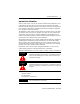
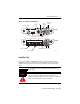
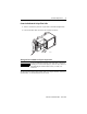
ControlNet Daughtercard 7 Figure 1 -- Set the Node Address I/O Status LED channel A connector NAP Module Status LED Node Address Switches 1788-CNF Network Status Indicators (A and B) 1788-CNFR 10’s 0’s Network Status Indicators (A and B) channel A connector channel B connector 31155 Install the Card Due to wide variation in available host devices, we cannot provide specific installation instructions in this document.
ControlNet Daughtercard ÿþýüûúùøù÷÷ùöõôóòññùóðúùïòûî 42822 42823 Connect the Card to the Network After you have installed the card, you can connect it to the network.
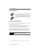
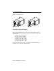
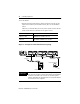
ControlNet Daughtercard 9 Connect to the Network Using a Fiber Cable 1. Remove and save the protective caps from the ControlNet daughtercards. 2. Connect the fiber cable connector to the module’s connector. 2 1 42821 òþûþøýù÷ôúùÿþñúûùðïóüõúùîïûùíþìëïûóùêìúûö÷þïø IMPORTANT To prevent inadvertent reversal of the trunk cable connections (resulting in incorrect status displays), check the drop cable for a label indicating the attached cable before you make your connection.
ControlNet Daughtercard To wire the module: • Hold down the latch and insert the Channel A zipcord connector into the duplex socket until the pins and latch lock into place (see the illustration below). Make sure you insert the blue pin (receive) of the zipcord connector into the left Rx and the black pin (transmit) into the right Tx socket.
ControlNet Daughtercard 11 When you connect the daughtercard to a ControlNet network, you should also refer to the ControlNet Fiber Media Planning and Installation Guide, publication CNET-IN001A-EN-P. See page 13 for information about status indicators. IMPORTANT If you use a non-redundant cable system, all ControlNet devices must be on the same channel, we recommend channel A.
ControlNet Daughtercard Wiring for the 1786-CP Connector Cable Connector 1 Wire Number Signal Mnemonic 1 ISO-GND 2 Connector 2 Signal Name Wire Number Signal Mnemonic Signal Name Isolated Ground 1 ISO-GND Isolated Ground N.C. No Connection 2 N.C.
ControlNet Daughtercard 13 Troubleshoot with the Status Indicators Status indicators provide information about the card and the network when you are connected via the fiber connectors. The following definitions and tables outline the possible states, explains what each state means to you, and indicates what action you should take, if any, to correct that state. Definition of terms: • steady - indicator is on continuously in the defined state.
ControlNet Daughtercard Table 1: Module and I/O Status Indicators for 1788-CNF Indicator Color Off Steady Red Module Status (MS) Probable Cause(s) Recommended Action •No power •Host is faulted •Host is holding daughtercard in reset •Check the power supply. •Ensure that the daughtercard is firmly seated in the slot. •Cycle power. If the indicator remains off, replace the daughtercard or the host. Major fault There is a hardware fault with the module. Cycle power.
ControlNet Daughtercard 15 Table 2: Network Status Indicators Indicator Color Probable Cause Recommended Action Off Channel disabled Program network for redundant media, if required. Steady Green Normal operation No action is required. Temporary network errors None, unit will self-correct. Node is not configured to go on line Make sure the configuration keeper node is present and working. Media fault Check media for broken cables, loose connectors, missing terminators, etc.
ControlNet Daughtercard Hazardous Location information The following information applies when operating this equipment in hazardous locations: Products marked “CL I, DIV 2, GP A, B, C, D” are suitable for use in Class I Division 2 Groups A, B, C, D, Hazardous Locations and nonhazardous locations only. Each product is supplied with markings on the rating nameplate indicating the hazardous location temperature code.
ControlNet Daughtercard 17 Informations sur l’utilisation de cet équipement en environnements dangereux : Les produits marqués « CL I, DIV 2, GP A, B, C, D » ne conviennent qu’à une utilisation en environnements de Classe I Division 2 Groupes A, B, C, D dangereux et non dangereux. Chaque produit est livré avec des marquages sur sa plaque d’identification qui indiquent le code de température pour les environnements dangereux.
ControlNet Daughtercard Specifications Characteristic Value Power Requirements 1788-CNF: 5V dc @ 440 mA (maximum) 1788-CNFR: 5V dc @ 450 mA (maximum) Conductor Category 22 Environmental Specifications This industrial control equipment is intended to operate in a Pollution Degree 2 environment, in overvoltage category II applications, (as defined in IEC publication 664A) at altitudes up to 2000 meters without derating. Also refer to the user manual for your host device.
ControlNet Daughtercard 19 Notes: Publication 1788-IN005A-EN-P - March 2001
Allen-Bradley is a trademark of Rockwell Automation. ControlNet is a trademark of ControlNet International. Publication 1788-IN005A-EN-P - March 2001 PN 957345-78 © 2001 Rockwell International Corporation. Printed in the U.S.A.