Installation Instructions ControlNet Daughtercards Catalog Numbers 1788-CNF, 1788-CNFR Inside . . .
ControlNet Daughtercards Important User Information Solid state equipment has operational characteristics differing from those of electromechanical equipment. Safety Guidelines for the Application, Installation and Maintenance of Solid State Controls (Publication SGI-1.1 available from your local Rockwell Automation sales office or online at http://literature.rockwellautomation.com) describes some important differences between solid state equipment and hard-wired electromechanical devices.
ControlNet Daughtercards 3 Environment and Enclosure ATTENTION This equipment is intended for use in a Pollution Degree 2 industrial environment, in overvoltage Category II applications (as defined in IEC publication 60664-1), at altitudes up to 2000 meters without derating. This equipment is considered Group 1, Class A industrial equipment according to IEC/CISPR Publication 11.
ControlNet Daughtercards European Hazardous Location Approval European Zone 2 Certification (The following applies when the product bears the EEx marking.) This equipment is intended for use in potentially explosive atmospheres as defined by European Union Directive 94/9/EC.
ControlNet Daughtercards 5 North American Hazardous Location Approval The following information applies when operating this equipment in hazardous locations: Informations sur l’utilisation de cet équipement en environnements dangereux: Products marked “CL I, DIV 2, GP A, B, C, D” are suitable for use in Class I Division 2 Groups A, B, C, D, Hazardous Locations and nonhazardous locations only.
ControlNet Daughtercards About the Daughtercards The 1788-CNF or 1788-CNFR ControlNet network daughtercard architecture defines a common hardware and software interface that several different network interface cards will support. This lets products that are designed to support the network daughtercard option support several Rockwell Automation networks. You can install the daughtercard in any host device that supports the ControlNet daughtercard.
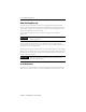
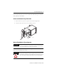
ControlNet Daughtercards I/O Status LED Channel A Connector NAP Module Status LED 7 Node Address Switches 1788-CNF Network Status Indicators (A and B) 1788-CNFR 10’s Channel A Connector Channel B Connector 0’s Network Status Indicators (A and B) 31155 Set the node address to a value between 1 and 99. For optimum throughput, assign addresses to your ControlNet nodes in a sequential order starting with 01. Node address 00 is not a valid ControlNet address.
ControlNet Daughtercards Install the Card Due to wide variation in available host devices, we cannot provide specific installation instructions in this document. For instructions on how to install the daughtercard in a host device, refer to the user manual for the particular host device. WARNING If you insert or remove the card while host power is on, an electrical arc can occur. This could cause an explosion in hazardous location installations.
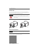
ControlNet Daughtercards 9 For more fiber cable options, refer to the ControlNet Fiber Media Planning and Installation Guide, publication CNET-IN001. Connect to the Network Using a Fiber Cable 1. Remove and save the protective caps from the ControlNet daughtercards. 2. Connect the fiber cable connector to the module’s connector.
ControlNet Daughtercards To wire the module: 1. Hold down the latch and insert the Channel A zipcord connector into the duplex socket until the pins and latch lock into place. 2. Make sure you insert the blue pin (receive) of the zipcord connector into the left Rx and the black pin (transmit) into the right Tx socket.
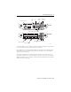
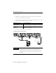
ControlNet Daughtercards 11 Connect to the Network Using a 1786-CP Cable IMPORTANT If you use a non-redundant cable system, all ControlNet devices must be on the same channel. We recommend channel A. Use the following wiring diagram to connect the programming terminal to the network using a 1786-CP cable. WARNING If you connect or disconnect the ControlNet network access port (NAP) cable with power applied to this module or any device on the network, an electrical arc can occur.
ControlNet Daughtercards Wiring for the 1786-CP Connector Cable Connector 1 Connector 2 Wire Number Signal Mnemonic Signal Name Wire Number Signal Mnemonic Signal Name 1 ISO-GND Isolated Ground 1 ISO-GND Isolated Ground 2 N.C. No Connection 2 N.C.
ControlNet Daughtercards 13 Troubleshoot the Daughtercards Status indicators provide information about the card and the network when you are connected via the fiber connectors. The following definitions and tables outline the possible states, explain what each state means to you, and indicate what action you should take, if any, to correct that state. Definition of terms: • steady - indicator is on continuously in the defined state.
ControlNet Daughtercards Indicator Color Off Probable Cause(s) • Check the power supply. • Host is faulted • Ensure that the daughtercard is firmly seated in the slot. • Host is holding daughtercard in reset Steady Red Major fault Flashing Firmware update in progress Red Node address switch change (Minor fault) Module Status (MS) Recommended Action • No power • Cycle power. If the indicator remains off, replace the daughtercard or the host. There is a hardware fault with the module.
ControlNet Daughtercards Indicator A or B 15 Color Probable Cause Recommended Action Off Channel disabled Program network for redundant media, if required. Steady Green Normal operation No action is required. Flashing Green/Off Temporary network errors None, unit will self-correct. Node is not configured to go on line Make sure the configuration keeper node is present and working. Flashing Red/Off Media fault Check media for broken cables, loose connectors, missing terminators, etc.
ControlNet Daughtercards Catalog Number Publication Name Publication Number 1786-RPA ControlNet Modular Repeater Adapter Installation Instructions 1786-IN013 1786-RPFS ControlNet Modular Repeater Short-distance Fiber Module Installation Instructions 1786-IN012 1786-TPR, 1786-TPS, 1786-TPYR, 1786-TPYS ControlNet Coax Tap Installation Instructions 1786-5.
ControlNet Daughtercards 17 Specifications Operational Temperature Storage Temperature Relative Humidity Vibration Operating Shock Non-Operating Shock Emissions ESD Immunity Radiated RF Immunity Enclosure Type Rating Power Requirements(1) 1788-CNF 1788-CNFR Power Consumption 1788-CNF 1788-CNFR Power Dissipation 1788-CNF 1788-CNFR Weight Wiring Category(2) IEC 60068-2-1 (Test Ad, Operating Cold), IEC 60068-2-2 (Test Bd, Operating Dry Heat), IEC 60068-2-14 (Test Nb, Operating Thermal Shock): This produ
ControlNet Daughtercards Certifications Certification Value Certifications(1) (when product is marked) UR CSA CSA CE C-Tick EEx CI (1) UL Recognized Component Industrial Control Equipment CSA Accepted Component for Process Control Equipment CSA Accepted Component for Process Control Equipment in Class I, Division 2 Group A,B,C,D Hazardous Locations European Union 89/336/EEC EMC Directive, compliant with: EN 50082-2; Industrial Immunity EN 61326; Meas./Control/Lab.
ControlNet Daughtercards 19 Notes: Publication 1788-IN005B-EN-P - October 2005
Rockwell Automation Support Rockwell Automation provides technical information on the web to assist you in using its products. At http://support.rockwellautomation.com, you can find technical manuals, a knowledge base of FAQs, technical and application notes, sample code and links to software service packs, and a MySupport feature that you can customize to make the best use of these tools.