Installation Instructions ControlNet Daughtercard Catalog Numbers 1788-CNC and 1788-CNCR This document describes how to install and configure the ControlNet 1788-CNC and -CNCR daughtercards. In this document, we use the term ‘the card’ to refer to both daughtercards collectively. When one card is different from the other, we refer to the daughtercard by name.
ControlNet Daughtercard Important User Information Important User Information Solid state equipment has operational characteristics differing from those of electromechanical equipment. Safety Guidelines for the Application, Installation and Maintenance of Solid State Controls (Publication SGI-1.1 available from your local Rockwell Automation sales office or online at http://www.ab.com/manuals/gi) describes some important differences between solid state equipment and hard-wired electromechanical devices.
ControlNet Daughtercard ATTENTION 3 Environment and Enclosure This equipment is intended for use in a Pollution Degree 2 industrial environment, in overvoltage Category II applications (as defined in IEC publication 60664-1), at altitudes up to 2000 meters without derating. This equipment is considered Group 1, Class A industrial equipment according to IEC/CISPR Publication 11.
ControlNet Daughtercard European Hazardous Location Approval European Zone 2 Certification (The following applies when the product bears the EEx Marking.) This equipment is intended for use in potentially explosive atmospheres as defined by European Union Directive 94/9/EC.
ControlNet Daughtercard 5 North American Hazardous Location Approval The following information applies when operating this equipment in hazardous locations: Informations sur l'utilisation de cet équipement en environnements dangereux: Products marked "CL I, DIV 2, GP A, B, C, D" are suitable for use in Class I Division 2 Groups A, B, C, D, Hazardous Locations and nonhazardous locations only.
ControlNet Daughtercard WARNING • If you connect or disconnect the communications cable with power applied to this module or any device on the network, an electrical arc can occur. This could cause an explosion in hazardous location installations. • If you insert or remove the card while host power is on, an electrical arc can occur. This could cause an explosion in hazardous location installations. • Be sure that power is removed or the area is nonhazardous before proceeding.
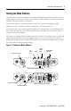
ControlNet Daughtercard 7 Setting the Node Address You must set two switch assemblies to configure the daughtercard with its unique network address. Figure 1 shows the location of the switches. These switches are read on powerup to establish the network address of the card. Set the node address to a value between 01 and 99. For optimum throughput, assign addresses to your ControlNet nodes in a sequential order starting with 01. Node address 00 is not a valid ControlNet address.
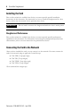
ControlNet Daughtercard Installing the Card Due to wide variation in available host devices, we cannot provide specific installation instructions in this document. For instructions on how to install the daughtercard in a host device, refer to the user manual for the particular host device. IMPORTANT Do not install or remove the daughtercard while the host is under power.
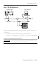
ControlNet Daughtercard 9 Figure 2 1788-CNCR Daughtercard example ControlNet node example ControlNet node trunk cable A trunk cable B example ControlNet node When you connect the daughtercard to a ControlNet network, you should also refer to this documentation: • ControlNet Coax Tap Installation Instructions, publication 1786-5.7 • ControlNet Coax Media Planning and Installation Guide, publication CNET-IN002 See page 14 for information about status indicators.
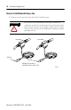
ControlNet Daughtercard Connect to the Network Using a Tap 1. Remove and save the dust cap(s) from the ControlNet tap(s). Do not allow any metal portions of the tap to contact any conductive material. If you disconnect the tap from the module, place the dust cap back on the straight or right angle connector to prevent the connector from accidentally contacting a metallic grounded surface. ATTENTION segment 1 trunk cable A trunk cable B segment 2 dust cap dust cap Note: 1788-CNC use trunk cable A.
ControlNet Daughtercard 11 2. Connect the tap’s straight or right-angle connector to the module’s BNC connector. If your network supports non-redundant media (1788-CNC or -CNCR) redundant media (1788-CNCR) 1. Connect the tap’s straight or right-angle connector to the channel A connector on the module (channel B on the 1788-CNCR is not used.)1 from trunk-cable A to channel A on the 1788-CNCR and from trunk-cable B to channel B on the 1788-CNCR.
ControlNet Daughtercard Connect to the Network Using a 1786-CP Cable Follow this illustration to connect a programming terminal to the network using a 1786-CP cable. Any ControlNet interface card A B 1786-CP cable 1 ControlNet network 1 The 1786-CP cable can be plugged into any ControlNet product's NAP to provide programming capability on the ControlNet network. A programming terminal connected through this cable is counted as a node and must have a unique address.
ControlNet Daughtercard 13 This table shows the wiring for the 1786-CP connector cable. Wire Number 1 2 3 4 5 6 7 8 Wire Number 1 2 3 4 5 6 7 8 Connector 1 Signal Mnemonic ISO-GND N.C. PTTX-H PTTX-L PTRX-L PTRX-H N.C. ISO-GND Connector 2 Signal Mnemonic ISO-GND N.C. PTRX-H PTRX-L PTTX-L PTTX-H N.C.
ControlNet Daughtercard Interpreting the Status Indicators Status indicators provide information about the card and the network when you are connected via the BNC connectors. Tables 1 and 2 on the following pages outline the possible states, explain what each state means to you, and indicate what action you should take, if any, to correct that state. Definition of terms: • steady - indicator is on continuously in the defined state.
ControlNet Daughtercard 15 Table 1 Interpreting Module and I/O Status Indicator Module Status (MS) Color Off Probable Cause(s) • No power • Host is faulted Steady Red Flashing Red • Ensure that the daughtercard is firmly seated in the slot. • Host is holding daughtercard • Cycle power. If the indicator remains off, replace the in reset daughtercard or the host. Major fault There is a hardware fault with the module. Cycle power. If the problem persists, replace the daughtercard.
ControlNet Daughtercard Table 2 Interpreting Network Status Indicator A or B (when viewed independently) Color Off Probable Cause Channel disabled Steady Green Flashing Green/Off Normal operation Temporary network errors Node is not configured to go on line Media fault Flashing Red/Off Flashing Red/Green Indicator A and B Color Off (when viewed together) Steady Red Alternating Red/Green Alternating Red/Off No other nodes present on network Incorrect network configuration Probable Cause S
ControlNet Daughtercard 17 Specifications Characteristic Value Operational Temperature IEC 60068-2-1 (Test Ad, Operating Cold), IEC 60068-2-2 (Test Bd, Operating Dry Heat), IEC 60068-2-14 (Test Nb, Operating Thermal Shock): 0 to 60°C (32 to 140°F) It is accebtable for the ambient slot temperature immediately surrounding this product to reach 85°C (185°F) maximum IEC 60068-2-1 (Test Ab, Un-packaged Non-operating Cold), IEC 60068-2-2 (Test Bb, Un-packaged Non-operating Dry Heat), IEC 60068-2-14 (Test Na,
ControlNet Daughtercard Weight 1788-CNC, 1788-CNCR Agency Certification (when product is marked) 0.1 Kg (0.
ControlNet Daughtercard 19 Notes: Publication 1788-IN002C-EN-P - April 2004
Rockwell Automation Support Rockwell Automation provides technical information on the web to assist you in using our products. At http://support.rockwellautomation.com, you can find technical manuals, a knowledge base of FAQs, technical and application notes, sample code and links to software service packs, and a MySupport feature that you can customize to make the best use of these tools.