User Manual ControlNet NetChecker Catalog Number 1788-CNCHKR Topic Page Important User Information 2 European Communities (EC) Directive Compliance 3 Additional Resources 3 Product Overview 4 Diagnostic Mode 7 Bargraph Mode 9 Operation 11 Reporting Examples 17 Additional Tips 20 Waveform Examples 21
ControlNet NetChecker Important User Information Solid-state equipment has operational characteristics differing from those of electromechanical equipment. Safety Guidelines for the Application, Installation and Maintenance of Solid State Controls (publication SGI-1.1 available from your local Rockwell Automation sales office or online at http://www.rockwellautomation.com/literature/) describes some important differences between solid-state equipment and hard-wired electromechanical devices.
ControlNet NetChecker 3 European Communities (EC) Directive Compliance If this product has the CE mark, it is approved for installation within the European Union and EEA regions and has been designed and tested to meet the following directive.
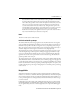
ControlNet NetChecker Product Overview The 1788-CNCHKR NetChecker is a hand-held tool for testing active ControlNet networks. It is pocket-sized and battery-powered for field use. The NetChecker helps commissioning and troubleshooting ControlNet installations by verifying signals on the ControlNet cabling. For example, installers are able to find shorts and termination faults by using the NetChecker. The tool is designed to evaluate the quality of the signal on the coaxial medium.
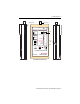
ControlNet NetChecker 5 BNC Connector SW1 (on the side) TRAFFIC INPUT Low Bat ; Output to Scope Signal (x1/4) GND Trigger Power Switch Diagnostic L M H 0 7 SW3 Threshold Node On Line 7 Max 6 OFF ON Push ON Node Finder Bargraph 5 Slow Edges 4 Illegal Framing 3 Poor Signal Quality 2 Pass/Fail Input Jack 1 Min SW2 Push ON Buzzer Ext Power 5VDC 0.
ControlNet NetChecker Table 1 - NetChecker Specifications Attribute 1788-CHNHKR Dimensions 152 x 83 x 33.5 mm (BNC connector not included) 164 x 83 33.5 mm (BNC connector included) Weight (with batteries) 250 grams (8.18 oz.) Environmental Operating Temperature: 0…50 °C (32…122 °F) Storage Temperature: -40…85 °C (-40…185 °F) Slide switch SW1 3-position power switch: • OFF disconnects the batteries. • ON turns on the tool permanently. • Push ON provides momentary power.
ControlNet NetChecker 7 TRAFFIC Status Indicator This bi-color status indicator at the top of the instrument has two functions: • Green (network activity)—When the NetChecker is connected to an active network and powered on this status indicator will turn green to indicate there is activity on the network. Only messages in which a Start Delimiter is detected in the header (and thus are considered valid) can cause this status indicator to turn green.
ControlNet NetChecker Status Indicator Functions When slide switch SW3 is in the Diagnostic (left) area of the front panel, the status indicators have the following functions: • Pass/Fail status indicator—Indicates the overall quality of the signal on the coaxial cable. Green when the input signal is clean, this status indicator will turn progressively red if one or more of the criteria of quality are violated.
ControlNet NetChecker 9 Note that when the Node On Line status indicator is red, it generally does not mean that the node itself is bad, but rather that the signal received by the NetChecker from this node is affected by a problem on the network. An impedance mismatch may cause some nodes to be received as good (Node On Line status indicator green) while others are received as bad (Node On Line status indicator red).
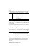
ControlNet NetChecker Bargraph Scale The Bargraph is not a precision voltmeter. The status indicators are numbered from 1 (lowest peak-to-peak voltage or Vpp) to 7 (highest Vpp). Also note that the scale is not linear. The following table shows the approximate peak-to-peak voltages indicated by each status indicator. Status Indicator Vpp Level Status Indicator GREEN if Status Indicator RED if 7 9.5 No green state Signal level > 9.5Vpp 6 7.5 7.5Vpp < signal level < 9.5Vpp No red state 5 5.
ControlNet NetChecker 11 Oscilloscope Output in Bargraph Mode In Node Signal Level Bargraph mode, the oscilloscope output is operational in the same way as in Diagnostic mode. In Global Bargraph mode, however, no trigger signal is provided since there can be no ControlNet node at address 00. Operation This section describes how to operate your NetChecker device. Install the Batteries Use a screwdriver to remove the two screws from the battery cover on the back of the NetChecker. Install the two 1.
ControlNet NetChecker Connect to the Network Connect the NetChecker to the network in one of these ways: • Use the provided cable and BNC T, as shown in the left example. This method requires you to break the trunk to install the BNC T, which disrupts a running system. The BNC T is intended for temporary use only. We do not recommend leaving the BNC T installed. • Use the provided BNC T with a 1786-TCAP tap and 1786-BNCP barrel connector, as shown in the right example.
ControlNet NetChecker 13 When you press the ON switch, the TRAFFIC status indicator should turn green to indicate that messages are being detected. The greater the volume of traffic seen on the network, the brighter the status indicator will be illuminated. If the status indicator remains off, the network is either inactive or the tested segment of cable is disconnected from the network. Check the cable and the connectors.
ControlNet NetChecker Faults and Their Origins The NetChecker checks for Poor Signal Quality, Illegal Framing, and Slow Edges. If a fault is detected when checking in the Diagnostic mode, the buzzer will sound and one or more of the three fault status indicators will blink red. The detection of Poor Signal Quality and Illegal Framing depends on the threshold setting on SW3.
ControlNet NetChecker 15 Poor Signal Quality Poor Signal Quality has the following indications. Status Indicator State TRAFFIC Green Slow Edges May also be blinking red Illegal Framing May also be blinking red Poor Signal Quality Blinking red Pass/Fail Yellow or red Buzzer Sounds A blinking Poor Signal Quality status indicator often indicates that signal reflections are present on the network.
ControlNet NetChecker Illegal Framing Illegal Framing has the following indications. Status Indicator State TRAFFIC Green Slow Edges May also be blinking red Illegal Framing Blinking red Poor signal Quality May also be blinking red Pass/Fail Yellow or red Buzzer Sounds Illegal Framing occurs if short messages or short between-message gaps have been detected. Illegal Framing detection is dependent on the threshold setting (SW3).
ControlNet NetChecker 17 Slow Edges is generally reported when a weak input signal with poor (slow) rising/falling edges is identified. This may occur with signals received from remote stations on long networks with a large number of nodes. In this case, Slow Edges detection is not influenced by the threshold setting on SW3. Make sure that the cable length versus number of nodes meets the ControlNet specification.
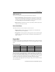
ControlNet NetChecker High Threshold Setting (lowest sensitivity level) Low Threshold Setting (highest sensitivity level) TRAFFIC TRAFFIC INPUT INPUT Low Bat Output to Scope Signal (x1/4 ) GND Trigger Power Switch Diagnostic Bargraph Signal (x1/4 ) GND Trigger Threshold Node On Line 7 Max 6 Node On Line 7 Max 6 5 4 Illegal Framing 3 Illegal Framing 3 Poor Signal Quality 2 Poor Signal Quality 2 Slow Edges Blinking Red 1 Green 1 1 Min Pass/Fail Red Push ON Buzzer Ext Po
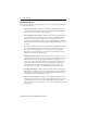
ControlNet NetChecker 19 TRAFFIC TRAFFIC INPUT INPUT Low Bat Low Bat Output to Scope Signal (x1/4 ) GND Trigger Power Switch Diagnostic Bargraph L M H Signal (x1/4 ) GND Trigger Threshold Node On Line 7 Max 6 OFF ON Push ON 0 Node Finder Illegal Framing 3 Poor Signal Quality 2 Pass/Fail Buzzer 1 1 Min Push ON Node On Line 7 Max 6 5 4 Illegal Framing 3 Poor Signal Quality 2 1 Min Push ON Ext Power 5VDC 0.
ControlNet NetChecker Additional Tips Use these tips to troubleshoot intermittent problems and maintain continuous network monitoring. Intermittent Problems Various intermittent problems are often are caused by the BNC connectors on the trunk cable, such as the center pin not crimped causing an unreliable contact. The NetChecker in Diagnostic mode is a valuable tool to help locate such problems. Read the NetChecker while subjecting each trunk connector or tap to a moderate mechanical stress.
ControlNet NetChecker 21 Waveform Examples This section shows the types of waveforms that may be seen on a ControlNet network. Ideal Transmitted Packet on ControlNet Network (as seen at transmitting node) 5 Mbps, Manchester Encoded Transmit Level: 8.2Vpp +/-1.3V +V 0V Tx Off -V t One Bit Time 200nS Waveform on Cable Ideal Received Packet on ControlNet Network (as seen at receiving node) 100nS 0 Volt 510mVpp min.
ControlNet NetChecker Typical Waveforms Good Signal Small Amount of Reflection Remote Station 6.000 V/D 100 nS/D Example of Waveform Seen When Network Is Improperly Terminated 2.
ControlNet NetChecker 23 Impedance mismatches cause reflections on the media: • Network not correctly terminated. • Impedance of coaxial cable not equal to 75 Ω. • High resistance of contact in connectors. • Incorrect network architecture. IMPORTANT Each coaxial segment must be terminated with a 1786-TCAP terminator at each end. Effect of Attenuation on Signal Edges 2.
Rockwell Automation Support Rockwell Automation provides technical information on the Web to assist you in using its products. At http://www.rockwellautomation.com/support, you can find technical manuals, technical and application notes, sample code and links to software service packs, and a MySupport feature that you can customize to make the best use of these tools. You can also visit our Knowledgebase at http://www.rockwellautomation.