User Manual EtherNet/IP and ControlNet to FOUNDATION Fieldbus Linking Devices
Important User Information Read this document and the documents listed in the additional resources section about installation, configuration, and operation of this equipment before you install, configure, operate, or maintain this product. Users are required to familiarize themselves with installation and wiring instructions in addition to requirements of all applicable codes, laws, and standards.
Table of Contents Important User Information . . . . . . . . . . . . . . . . . . . . . . . . . . . . . . . . . . . . . . . . 2 Table of Contents Preface Introduction. . . . . . . . . . . . . . . . . . . . . . . . . . . . . . . . . . . . . . . . . . . . . . . . . . . . . . . 5 About the Linking Devices . . . . . . . . . . . . . . . . . . . . . . . . . . . . . . . . . . . . . . 5 Network Diagrams . . . . . . . . . . . . . . . . . . . . . . . . . . . . . . . . . . . . . . . . . . . . . . . . .
Table of Contents Connect Safe Mode . . . . . . . . . . . . . . . . . . . . . . . . . . . . . . . . . . . . . . . . . . . Start the Back-up LAS Master (Already Configured) . . . . . . . . . . . . Reconnect Two Separate Running LAS Devices . . . . . . . . . . . . . . . . . Swap Out Linking Devices . . . . . . . . . . . . . . . . . . . . . . . . . . . . . . . . . . . . 46 46 47 47 Chapter 3 Logix Assemblies Input . . . . . . . . . . . . . . . . . . . . . . . . . . . . . . . . . . . . . . . . . . . . . . .
Table of Contents Master Mode 11 Master Mode 12 Master Mode 13 Master Mode 14 Master Mode 15 Master Mode 16 ................................................. ................................................. ................................................. ................................................. ................................................. .................................................
Table of Contents 4 Rockwell Automation Publication 1788-UM057B-EN-P - September 2014
Preface Introduction This user manual describes the installation and operation of the 1788-EN2FFR and 1788-CN2FFR linking devices. About the Linking Devices The 1788-EN2FFR linking device provides a gateway between an EtherNet/IP network and a single segment FOUNDATION Fieldbus H1 layer. The 1788-CN2FFR linking device provides a gateway between a ControlNet network and a FOUNDATION Fieldbus network. In this manual, both modules are referred to as the linking device.
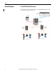
Preface Network Diagrams 1788-EN2FFR EtherNet/IP Network The diagram below is an example of how a 1788-EN2FFR linking device could be used with an EtherNet/IP network..
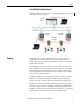
Preface 1788-CN2FFR ControlNet Network This diagram shows an example of how a 1788-EN2FFR linking device could be used with a ControlNet network. ControlLogix Controller 1788-CN2PAR Linking Device 1788-CN2PAR Linking Device 1788-FBJB4R Junction Boxes Features The AOP provides an intuitive graphical interface to configure devices.
Preface Built-in power conditioners and protection are provided, which helps to minimize installation space requirements. The H1 segment is divided between two physical ports (A and B) with individual protection and a supply of 500 mA per port. See H1 Network Connections on page 14. The basic diagnostics of the linking device and the field devices, is found in the input assemblies. Advanced configuration is found only through the AOP.
Preface Environment and Enclosure ATTENTION: Environment and Enclosure • This equipment is intended for use in a Pollution Degree 2 industrial environment, in overvoltage Category II applications (as defined in IEC 606641), at altitudes up to 2000 m (6562 ft) without derating. • This equipment is not intended for use in residential environments and may not provide adequate protection to radio communication services in such environments. • This equipment is supplied as open-type equipment.
Preface European Hazardous Location Approval The following applies when the product bears the marking. This equipment is intended for use in potentially explosive atmospheres as defined by European Union Directive 94/9/EC and has been found to comply with the Essential Health and Safety Requirements relating to the design and construction of Category 3 equipment intended for use in Zone 2 potentially explosive atmospheres, given in Annex II to this Directive.
Preface NNorth American Hazardous Location Approval The following information applies when operating this equipment in hazardous locations. The following information applies when operating this equipment in hazardous locations: Informations sur l'utilisation de cet équipement en environnements dangereux: Products marked "CL I, DIV 2, GP A, B, C, D" are suitable for use in Class I Division 2 Groups A, B, C, D, Hazardous Locations and nonhazardous locations only.
Preface Additional Resources These documents contain more information about related products from Rockwell Automation®. Resource Description FOUNDATION Fieldbus Linking Devices Technical Data, publication 1788-TD001 Provides technical data and specifications for the FOUNDATION Fieldbus linking devices.
Chapter 1 Installation Hardware ATTENTION: Do not wire more than one conductor on any single terminal. Dimensions 80 mm (3.15 in) 136 mm (5.35 in) 152 mm (5.98 in) Power Connection To comply with the CE Low Voltage Directive (LVD), this equipment must be powered from a source compliant with Safety Extra Low Voltage (SELV) or Protected Extra Low Voltage (PELV). To comply with UL restrictions, this equipment must be powered from a source compliant with Class 2 or Limited Voltage/Current.
Chapter 1 Installation We recommend a 24…32V DC power supply for the linking device to operate correctly. No additional power supplies or power conditioners are required. The power supply connection is described here. Tighten DC Power connections to a torque of 0.22…0.25Nm (2…2.2 lb-in). IMPORTANT Do not use additional power supplies or power conditioners with the 1788-EN2FFR and 1788-CN2FFR linking devices.
Installation Rockwell Automation Publication 1788-UM057B-EN-P - September 2014 Chapter 1 15
Chapter 1 Installation ControlNet and EtherNet/IP Connections Two BNC connectors on the base of the 1788-CN2FFR linking device provide connections for single or dual ControlNet media. The 1788-EN2FFR linking device uses an RJ45 connector to connect to an EtherNet/IP network. The dual port EtherNet/IP switch on the 1788-EN2FFR linking device provides connections for multiple Ethernet topologies, including device level ring (DLR).
Installation Set the Linking Device Network Address Chapter 1 This section describes the network address switches. Hardware Switches Location The hardware switches are located under the front cover of the linking device. Use the Page button to toggle between different diagnostics on the display. Set the ControlNet Node Address To set the ControlNet node address of the 1788-CN2FFR linking device, use the hardware switches behind the front cover.
Chapter 1 Installation Set the EtherNet/IP Address The linking device ships with BOOTP enabled. To set the IP address of the 1788-EN2FFR linking device, use a BOOTP server or use the hardware switches. IMPORTANT 18 Power down the linking device before changing the Ethernet switch settings. The IP address is set during powerup.
Installation Chapter 1 Ethernet Switch Settings This table describes the Ethernet switch settings. Ethernet Switch Setting Description To set the IP address of the linking device to the 192.168.1.xxx sub net, set the switches to the required last three digits. In this example, the linking device will start up with IP address: 192.168.1.123. To set the IP address of the linking device via a BOOTP server, set the switches to 888 (factory default setting).
Chapter 1 Installation Software Installation You need the AOP for the Studio 5000 Logix Designer application to configure and manage the linking device. The installation of the AOP includes the HSProcessUtility that is used to manage DTMs and DD service libraries. See Appendix B. For the latest compatible software information and to download the AOP, see the Product Compatibility and Download Center at http://www.rockwellautomation.com/rockwellautomation/support/ pcdc.page#/tab2.
Chapter 2 Set Up in the Studio 5000 Logix Designer Application Add the 1788-EN2FFR Linking Device to the I/O Tree The 1788-EN2FFR linking device must be added to the I/O tree of the Logix controller. The linking device must be added to an Ethernet bridge, such as an Allen-Bradley® 1756-EN2T or 1756-EN2TR module. Follow these steps to add the linking device to the I/O tree of the Logix controller. This example uses the 1756-EN2TR module. 1. Right-click the Ethernet bridge and choose New Module. 2.
Chapter 2 Set Up in the Studio 5000 Logix Designer Application 4. Set the RPI for the linking device. IMPORTANT The recommended RPI is 1/2 the macrocycle time. Calculate the macrocycle by calculating the total response time of all field devices on the segment and then add 100…200 ms for class 2 (DTM message) data. If the RPI is too low, class 1 data (PVs and status) does not update each cycle, and class 2 data responses can be slow. 5. Click OK to add the linking device to the I/O tree.
Set Up in the Studio 5000 Logix Designer Application Chapter 2 4. Set the RPI for the linking device. IMPORTANT The recommended RPI is 1/2 the macrocycle time. Calculate the macrocycle by calculating the total response time of all field devices on the segment and then add 100…200 ms for class 2 (DTM message) data. If the RPI is too low, class 1 data (PVs and status) does not update each cycle, and class 2 data responses can be slow. 5. Click OK to add the linking device to the I/O tree.
Chapter 2 Set Up in the Studio 5000 Logix Designer Application 3. Select the communication path to the ControlNet network, select the ControlNet port, and click OK. The following pop-up window appears while RSNetWorx browses the network. Once complete, all devices on the network are displayed in the graphic window on the right side of the window. 4. Right-click any white space around the graphics and select Enable Edits. 5. Right-click any white space around the graphics and select Properties.
Set Up in the Studio 5000 Logix Designer Application Chapter 2 6. On the Networks Parameters Tab, update the Max Unscheduled Address if you are sure that the allocated range is less than 99. 7. Click OK. 8. Right-click any white space around the graphics and choose Download to Network. 9. Select the correct save option for your configuration and click OK. 10. Enter a suitable file name. 11. Click Yes to download the configuration.
Chapter 2 Set Up in the Studio 5000 Logix Designer Application Linking Device Configuration Using the AOP Once the linking device has been added to the config tree, you can access the property settings. Right-click the linking device and select Properties. Then click the Configuration tab as shown in Figure 1. Once the linking device is connected to the controller, you can see the linking device in the Configuration tab.
Set Up in the Studio 5000 Logix Designer Application Chapter 2 LAS The LAS icon indicates if the master is the LAS that requests and receives live data from each field device, or if the master is the back-up LAS. (The back-up LAS has a red X over the icon.) See Redundant Master Setup on page 43 for more information. Config Tree Once you have configured the slot for a device (even if not downloaded yet), the device appears in the config tree.
Chapter 2 Set Up in the Studio 5000 Logix Designer Application Master Configuration 1. Open the master configuration page from the config tree to access the linking device master configuration settings. 2. Choose the Topology for the master linking device. 3. Enter the configuration values. 4. Click the Download Config button to download the settings to the linking device. The settings are stored in nonvolatile memory in the linking device. 5.
Set Up in the Studio 5000 Logix Designer Application Chapter 2 Max Scan Address When the linking device is operating, a background scan constantly probes each unused node number to see if any new field devices were connected. The background scan runs to the max scan address, then restarts at one. Slave Retry Limit The slave retry limit sets the number of times the H1 Master re-requests data before dropping the connection. The default setting is 5. IMPORTANT Do not modify the default setting.
Chapter 2 Set Up in the Studio 5000 Logix Designer Application Auto MacroCycle Calculates the Macro Cycle based on the configured field devices and the number of PVs configured. A window is also added for class II data communication. Advanced Opens the Advanced Settings window. Load Defaults Resets the configuration settings to their default values. Update Master Time Update the master time to local computer time. Download Schedule Download schedule to linking device.
Set Up in the Studio 5000 Logix Designer Application Chapter 2 Figure 2 - Master Advanced Configuration Screen Auto MacroCycle Click the Auto MacroCycle button on the master configuration page to calculate the recommended MacroCycle for the current linking device (see Master Configuration on page 28).
Chapter 2 Set Up in the Studio 5000 Logix Designer Application Field Device Configuration The overview page on the configuration tab displays the field device live list with colored icons that depict the status of each field device (see page 26). If the Studio 5000 Logix Designer application is online with the 1788-CN2FFR/1788EN2FFR link master correctly configured, the attached field devices appear in the live list.
Set Up in the Studio 5000 Logix Designer Application Chapter 2 The color of the text indicates if the online device has the same node address and tag as the offline configured device. • If the text is black, the online and offline node address and tag name match. • If the text is red, the online and offline node address and tag name do not match. Add New Use this function to add field devices when the linking device is not connected to the field device.
Chapter 2 Set Up in the Studio 5000 Logix Designer Application Configure Launches the field device block configuration screen that is used to configure each field device. Auto Configure Online IMPORTANT Requires the field device to be online. You can right-click on a device (of which the DD files are registered) and choose the Auto Configure Online option. A configuration is applied for basic operation of the field device. • The AOP adds a resource block and sets the target mode to auto.
Set Up in the Studio 5000 Logix Designer Application Chapter 2 Copy and Paste After the device configuration is done, you can copy and paste the configuration to speed up the configuration process. Move You can move a device in the live list to another field device index even if the devices have been configured and are providing process variables. Remove A device configuration can also be removed (deleted).
Chapter 2 Set Up in the Studio 5000 Logix Designer Application Field Device Block Configuration You can configure the field device blocks from the block configuration view. Choose the Configuration option of the device in the config tree, or from the right-click menu in the live list. Configuration is device-centric and performed in a graphical view using blocks, wires, and connectors (see Figure 5 on page 34).
Set Up in the Studio 5000 Logix Designer Application Chapter 2 Add a Block Blocks are defined by the field device manufacturer and described in the DD files. There are three classes of blocks: R – Resource Block T – Transducer Block F – Function Block Only function blocks have ports that are used to transfer data to and from the block: • Ports on the left of the function blocks are inputs. • Ports on the right of the function blocks are outputs.
Chapter 2 Set Up in the Studio 5000 Logix Designer Application Adjust Block Parameters To change the parameters of a block, right-click the title portion of the block and choose Parameters. To enable a parameter for editing, click the box in the En column. A green check mark indicates the parameter is enabled for editing. Different parameters will have different classes as shown in Table 4.
Set Up in the Studio 5000 Logix Designer Application Chapter 2 Add a Connector A connector enables transfer of data between the block of the field device and the data structure in the controller, or between field device blocks on the same segment. Data transfers between segments are performed via the controller. Follow these steps to add a connector. 1. To add a connector, right-click in the window and choose New Connector. 2.
Chapter 2 Set Up in the Studio 5000 Logix Designer Application The field device index, PV slot, and data type define where the connector points to in the data structure of the controller tags. Figure 6 - Example of a Field Device Index • For Input : I.PV connectors, the data types of float and integer both connect to PVReal in the input image, while binary data types connect to PVBinary. • For Output : O.
Set Up in the Studio 5000 Logix Designer Application Chapter 2 Add Wires Wires are used to connect input and output ports on the blocks to other ports or connectors. Follow these steps to add a wire. 1. To add a wire, right-click in the window and choose New Wire. 2. Drag the ends of the wires to the docking points on the block and the connectors. Download the Configuration When the configuration is complete, click the Download button to download the configuration to the field device.
Chapter 2 Set Up in the Studio 5000 Logix Designer Application Once the download is done and the device is providing process variables, the device will be green in the configuration tree and the live list. If the device is not producing data (for example, incorrect configuration) the device will be blue in the configuration tree and the live list. Go Online Click the Go Online button to see process variables and change parameters in real time. Click a parameter to change it in real time.
Set Up in the Studio 5000 Logix Designer Application Scheduling and the LAS Chapter 2 The 1788-CN2FFR/1788-EN2FFR linking device generates the LAS schedule, which determines when each function block executes and transmits data. Newly added field devices are automatically added to the schedule, and removed from the schedule when removed from the live list.
Chapter 2 Set Up in the Studio 5000 Logix Designer Application We recommend you use the given AOI when using redundant masters. The AOI swaps between masters when one fails and automatically updates the destination PV with the back-up master data. Only one of the masters is the LAS that requests and receives live data from each field device. • If the device is the LAS, the device icon is displayed without a cross (see page 26). • If the device is the back-up LAS, the device icon is displayed with a cross.
Set Up in the Studio 5000 Logix Designer Application Chapter 2 Redundant Master Mismatch If the two masters are not synchronized (for example, there is a configuration mismatch) one of the following errors on the back-up LAS is displayed. • Master + Device Config Mismatch indicates that there is a difference between the LAS and back-up LAS master configuration. • Device Config Mismatch indicates that there is a difference in at least one of the field devices between the LAS and back-up LAS configuration.
Chapter 2 Set Up in the Studio 5000 Logix Designer Application MultiMaster Connecting Procedures To avoid communication loss, or a field device going to the visitor address range, follow the MultiMaster connection procedures in this section. Connect Safe Mode The Connect Safe mode is used in the Reconnect Two Separate Running LAS Devices on page 47 and Swap Out Linking Devices on page 47 procedures. To enter the Connect Safe mode, hold the Page button for at least 5 seconds.
Set Up in the Studio 5000 Logix Designer Application Chapter 2 Reconnect Two Separate Running LAS Devices If two masters are configured on a network (one on each end) and the cable between them is broken, some devices will be connected to one master, and the remaining devices will be connected to the other master. See master modes 9, 12, and 15 in Appendix D. Follow these steps to connect the two H1 segments. 1.
Chapter 2 48 Set Up in the Studio 5000 Logix Designer Application Rockwell Automation Publication 1788-UM057B-EN-P - September 2014
Chapter 3 Logix Assemblies Input The linking device uses four CIP connections for the 16 field devices. Connection A has the master instance and four field devices. The other connections (B, C, and D) have only the four field devices. All device assemblies are identical. Figure 9 - Example of Linking Device Connections Tag Data Structure Master Device Tag Structure This section describes the values on the elements in the master device status tag structure.
Chapter 3 Logix Assemblies Bus A/BTripped If too much current (> 500 mA) is drawn on Bus A or Bus B, a trip occurs and the bus is no longer functional. The trip is indicated in the input image. NewFieldDevice If a new field device is found which is not in the configuration of the H1 master, a new field device bit is set. LinkActiveScheduler This bit indicates if the current device is the LAS or the back-up LAS (set indicating that the linking device is the LAS).
Logix Assemblies Chapter 3 BusA/BTerminated The master mode setting sets the termination for H1 ports A and B. For example, if the mode setting is Master Mode 0 - Single Master, A Bus Only, then A is enabled and terminated (see page 85). Field Device Tag Structure This section describes the elements of the field device tag structure. FFNode The node value specifies the number of the field device.
Chapter 3 Logix Assemblies PVReal1…PVReal8 This element contains the process variable (PV) float or integer value from the field device. Each field device can have a maximum of eight real PVs. PVBinary1…PVBinary8 This element contains the process variable (PV) Boolean value from the field device. Each field device can have a maximum of eight binary PVs.
Logix Assemblies Chapter 3 PVDiagnostics This tag contains the diagnostics information that is associated with each PV. Output This section describes the values on the field device output status screen. Field Device Output Values PVReal1…PVReal8 For a field device that requires an output, the data must be updated in the output image of that field device. If the data type for the connector is set to Float, then the data for that connector is read from the real value in the output image.
Chapter 3 Logix Assemblies PVBinary1…PVBinary8 For a field device that requires an output, the data must be updated in the output image of that field device. If the data type for the connector is set to Boolean, then the data for that connector is read from the binary value in the output image. PVStatus1…PVStatus8 If the connector for the PV output is set to have a status, you must put a status in the output image that will be sent with the process variable.
Chapter 4 Diagnostics Status Screen The diagnostic status provides basic device data and statistics. Click Status in the config tree to view basic data and statistics for the device. Status The connectivity status of the linking device. Value Description 80…100 Good 41…79 Uncertain 0…40 Bad Tag The tag name that is stored in the field device. Ident The identity of field device. Device The field device type. Vendor The field device vendor.
Chapter 4 Diagnostics The count of good quality reply packets that are received from the field device. (Cyclic Redundant Code [CRC] check passed.) Bad CRC Packets The count of reply packets that are received from the field device that were rejected because the CRC check failed. No Replies The count of communication request to which the field device did not respond. Success Rate The rate of good replies to the number of requests for the last 100 requests.
Diagnostics PV Data Screen Chapter 4 If a field device has been configured and scheduled, its scheduled PV values are displayed here. The name of the function block parameter that produces or consumes the data is also displayed. Table 6 - PV Status Colors PV Status Status Color PVStatus ≥ 0x80 Green = good 0x40 ≤ PVStatus < 0x80 Orange = uncertain PVStatus < 0x40 Red = bad Click PV Data in the config tree to view the PV data for the device.
Chapter 4 Diagnostics The Web Server To view detailed status and diagnostic information for the device in the web server, enter the IP address of the device into the address field of a web browser and press Enter. IMPORTANT 58 If data is not being updated, turn off page caching or try a different web browser.
Diagnostics Device Type Manager (DTM) Chapter 4 Use the HSThinFrame to open the device DTM in the Studio 5000 Logix Designer application. The DTM is read-only when opened in the Studio 5000 Logix Designer application. IMPORTANT The correct DTM must be installed and the HSProcessUtility DTM Catalog must be updated for the correct DTM to display in the pull-down list. Follow these steps to open the DTM. 1. Click Advanced in the config tree. 2. Choose the DD revision from the pull-down list. 3.
Chapter 4 Diagnostics 5. View the selected device information.
Appendix A Linking Device Display Status The display of the linking device provides status and diagnostic data in one of three page formats: main page, H1 master page, or field device page. Use the display Page button behind the front cover to scroll through the pages (see Figure 8 on page 46 for location of the Page button). Main Page The main page is the default display, and the linking device returns to this page after 10 seconds. H1Bus A/B: Displays the bus voltages on each port.
Appendix A Linking Device Display Status H1 Master Page The next page that is accessed by the Page button is the H1 Master page. Bus A/B: Displays the bus voltages, currents, and bus status. Temperature: Displays the internal temperature of the linking device. External Pwr: Displays the power supply voltage. FF Node: Displays the H1 node address for the master (default 16). BusA/B Enabled: H1 Bus A or H1 Bus B is enabled for communication.
Linking Device Display Status Appendix A Pckt Recv: Displays the total number of data packets that are received from the field device. Bad CRC: Displays the total number of bad CRC packets received. No Reply: Displays the total number of data requests to which the field device did not respond. Signal Quality: Displays the quality of the waveform for the field device by evaluating slew rate, amplitude, distortion, noise, and balance.
Appendix A Linking Device Display Status Notes: 64 Rockwell Automation Publication 1788-UM057B-EN-P - September 2014
Appendix B HSProcessUtility Use the HSProcessUtility Follow these steps to use the HSProcessUtility to add a device description to a field device. 1. Click the HSProcessUtility icon in the AOP and click Launch HSProcessUtility. TIP You can also click the refresh catalog option to refresh the device catalog once a DD file has been added. The HSProcessUtility opens. Because the same utility is used to register GSD files (PROFIBUS PA) and DTMs, these options are still in the menu bar. 2.
Appendix B HSProcessUtility 3. Select the binary file, the appropriate symbol file, and the correct version of the capability file. A new file is generated and the library directory is updated. TIP Before the field device can be configured in the AOP, the catalog must be refreshed. 4. Click the HSProcessUtility icon and choose Refresh Catalog.
HSProcessUtility Appendix B 5. Install the device DTMs from the vendors, then go to the DTM tab in HSProcessUtility and click Update Catalog.
Appendix B HSProcessUtility Notes: 68 Rockwell Automation Publication 1788-UM057B-EN-P - September 2014
Appendix C Field Device Block Configuration Examples Overview This appendix provides examples of how to use field bus output devices with the linking device. Each example starts from an empty live list, adds the device to the network, and configures an analog output (AO) or discreet output (DO) function. The purpose of these examples is to place the AO or DO function block in the Cas mode, so the values entered in CAS_IN are processed into the SET_POINT value.
Appendix C Field Device Block Configuration Examples AO Function Block Example This example describes the steps that are used to configure an AO function block for the linking device. The linking device tag name in this example is SMAR FI302. 1. Add the linking device to the field bus network. 2. Right-click the linking device and choose Auto Configure Online.
Field Device Block Configuration Examples Appendix C 3. Click the Go Online button. 4. Right-click the resource function block and choose Parameters. Verify that the correct DD files were enabled. 5. Scroll down to Index rows 10, 11, 12, and 13. 6. Check the En column for Index rows 10, 11, 12, and 13. A green check displays in the box.
Appendix C Field Device Block Configuration Examples 7. Verify that the Dev_Rev and DD_REV in the Parameters screen matches the Rev and DDRev revisions in the HSProcessUtility (compare Figure and Figure 7). 8. Use the tools in the Configuration screen to build the configuration as shown in Figure . See Field Device Block Configuration on page 36 for general field device block configuration information.
Field Device Block Configuration Examples Appendix C 9. Click the download button to download the AO function block to the linking device. The download operation completes without errors. 10. Click OK.
Appendix C Field Device Block Configuration Examples 11. Click the Go Online button. 12. Right-click the Analog Output function block. 13. Choose Parameters. The linking device parameters are displayed.
Field Device Block Configuration Examples Appendix C 14. Under MODE_BLK > PERMITTED, right-click the Value column and select Cas. 15. Click OK to add the Cas mode. 16. Under MODE_BLK > TARGET, right-click the Value column and select Cas and Auto. 17. Click OK to add the Cas+Auto mode.
Appendix C Field Device Block Configuration Examples 18. Verify that the MODE_BLK > TARGET value is Cas + Auto and the MODE_BLK > ACTUAL value is Auto. 19. In the parameter screen, scroll down to parameters CAS_IN and BKCAL_OUT. 20. Verify that the BKCAL_OUT > STATUS in the Live column indicates a NotInvited condition. Before the output control loop can be initialized, the NotInvited condition must be cleared.
Field Device Block Configuration Examples Appendix C 21. Set the value of the controller tag that is associated with the quality of CAS_IN (connector PV:O.1) status parameter (PVx_GoodCascade) to the value 1. 22. Verify that the NotInvited status has been replaced by the new status, InitializationRequest. The InitializationRequested must receive a response. 23. Set the value of the Controller Tag associated with the substatus of CAS_IN (connector PV:O.
Appendix C Field Device Block Configuration Examples The InitializationRequested status in BKCAL_OUT > STATUS > Live column is cleared and replaced by the value, NonSpecific. The CAS_IN > STATUS > Live column displays a status of InitializationAcknowledge.
Field Device Block Configuration Examples Appendix C 24. Verify that the AO function block MODE_BLK > ACTUAL > Live column displays Cas. 25. Set the CAS_IN (PV:O.1) value to 50%. 26. Verify that the BKCAL_OUT (PV:I.1) and OUT (PV:I.2) values change as required (50% equals 12 mA at the OUT parameter). The AO function block is now created, initialized, and operating correctly.
Appendix C Field Device Block Configuration Examples DO Function Block Example This example describes the how to configure a DO function block for the linking device. The device that is used in this example is FPAC_2. 1. Add the linking device to the field bus network. 2. Add a DO function block to the configuration. TIP 80 You can delete other function blocks and connections.
Field Device Block Configuration Examples Appendix C 3. Make connections to CAS_IN_D, OUT_D, and BKCAL_OUT_D. 4. Click the Download button to download the DO function block to the linking device. The download operation completes without errors. 5. Click OK.
Appendix C Field Device Block Configuration Examples 6. Click the Go Online button. 7. Right-click the Discreet Output function block. 8. Choose Parameters. The linking device parameters are displayed. 9. In the Parameters screen, scroll down to parameters CAS_IN_D and BKCAL_OUT_D.
Field Device Block Configuration Examples Appendix C 10. Verify that the BKCAL_OUT_D > STATUS in the Live column indicates a NotInvited condition. Before the output control loop can be initialized, the NotInvited condition must be cleared. 11. Set the value of the controller tag that is associated with the quality of BKCAL_OUT_D (connector PV:O.1) status parameter (PVx_GoodCascade) to the value 1. 12. Verify that the NotInvited status has been replaced by the new status, InitializationRequest.
Appendix C Field Device Block Configuration Examples 13. Set the value of the Controller Tag associated with the substatus of CAS_IN_D (connector PV:O.1) status parameter (PV1_SubStatus) to the value 1, which is InitializationAcknowledge. 14. Verify that the DO function block MODE_BLK > ACTUAL > Live column displays Cas. The DO function block is now created, initialized, and operating correctly.
Appendix D H1 Topology Master Mode 0 Single Master A Bus Only Terminated at the linking device. Master Mode 1 Single Master A Bus Only Not terminated at the linking device. Master Mode 2 Single Master B Bus Only Terminated at the linking device.
Appendix D H1 Topology Master Mode 3 Single Master B Bus Only Not terminated at the linking device. Master Mode 4 Single Master Dual Bus Terminated at the linking device. Master Mode 5 Single Master Dual Bus Not terminated at the linking device. Master Mode 6 Single Master Split Bus Terminated at the linking device.
H1 Topology Master Mode 7 Appendix D Single Master Split Bus Not terminated at the linking device. Master Mode 8 Single Master Ring Bus Master Mode 9 MultiMaster A Bus Only Terminated at the linking devices. Master Mode 10 MultiMaster A Bus Only Shared termination at the linking devices.
Appendix D H1 Topology Master Mode 11 MultiMaster A Bus Only Not terminated at the linking devices. Master Mode 12 MultiMaster B Bus Only Terminated at the linking devices. Master Mode 13 MultiMaster B Bus Only Shared termination at the linking devices. Master Mode 14 MultiMaster B Bus Only Not terminated at the linking devices.
H1 Topology Master Mode 15 Appendix D MultiMaster Dual Bus Terminated at the linking devices. Master Mode 16 MultiMaster Dual Bus Shared termination at the linking devices.
Appendix D H1 Topology Notes: 90 Rockwell Automation Publication 1788-UM057B-EN-P - September 2014
Glossary The following terms and abbreviations are used throughout this manual. For definitions of terms not listed here, refer to the Allen-Bradley Industrial Automation Glossary, publication AG-7.1. 1788-EN2FFR linking device Provides a gateway between EtherNet/IP and a single segment FOUNDATION Fieldbus H1 layer. 1788-CN2FFR linking device Provides a gateway between ControlNet and FOUNDATION Fieldbus (FF).
Glossary ControlNet network An open control network that uses the producer/consumer model to combine the functionality of an I/O network and peer-to-peer network, while providing high-speed performance for both functions. cycle Scanning of inputs, execution of algorithms and transmission of output values to devices. device description (DD) Abbreviated as DD, this is a set of files (CFF, SYM, and FFO) that describes the parameter capabilities of a fieldbus device.
Glossary host Control system that has FOUNDATION fieldbus capabilities to configure and operate FOUNDATION fieldbus segments. There are several classes of Host systems: • Class 61 - Integrated Host - Primary, or process Host that manages the communication and application configuration of all devices on the network. • Class 62 - Visitor Host - Temporary, on process Host with limited access to device parameterization.
Glossary online Perform tasks, such as configuration, while the Host system is communicating with the field devices. PV Acronym for Process Variable, which is the primary value. resource block (RES) This block controls the linking device. It contains data specific to the linking device’s hardware. All data is modeled as contained, so there are no links in this block.
Glossary VCR Acronym for Virtual Communication Relationship. Configured application layer channels that provide for the transfer of data between applications. FOUNDATION Fieldbus describes three types of VCRs: Publisher/Subscriber, Client/Server, and Source/Sink.
Glossary Notes: 96 Rockwell Automation Publication 1788-UM057B-EN-P - September 2014
Index Numerics 1756-CNB ControlNet bridge 22 1756-CNBR ControlNet bridge 22 1756-EN2T Ethernet bridge 21 1756-EN2TR Ethernet bridge 21 1788-CN2FFR ControlNet network 7 1788-EN2FFR EtherNet/IP network 6 A add linking device to I/O tree 22, 23 add new field device 33 add-on-profile 20 advanced configuration 8 advanced settings 30 AO function block example 70 AOP install file 20 version 20 Auto MacroCycle 30, 31 Auto MacroCycle calculation 31 auto reset trip 29 B background scan 29 backup linking device 43 b
Index display status field device page bad CRC 63 data packet transfer success rate 62 device tag name 62 FF node 62 field device status 62 no reply 63 pckt recv 63 pckt send 62 signal quality 63 status 62 H1 master page bus A/B 62 busA/B enabled 62 busA/B term 62 busA/B tripped 62 external pwr 62 FF node 62 temperature 62 main page bus A tripped 61 bus B tripped 61 bus voltages 61 communication quality 61 H1Bus A/B 61 IP address or BOOTP 61 new device found 61 Ok 61 redundancy err 61 redundancy ok 61 SAFE
Index terminated 87 B bus only not terminated 88 shared termination 88 terminated 88 dual bus shared termination 89 terminated 89 H1 topology, single master A bus only mon-terminated 85 terminated 85 B bus only non-terminated 86 terminated 85 dual bus non-terminated 86 terminated 86 ring bus 87 split bus non-terminated 87 terminated 86 HSProcessUtility 20, 31 HSThinFrame 59 PVBinary1...PVBinary8 52 PVDiagnostics 53 PVReal1...
Index module properties, configuration tab config tree 27 LAS 27 live list 26 shortcuts 27 visitor list 26 N network publication connectors 39 subscription connectors 39 network connection, H1 14 network diagrams ControlNet network 7 EtherNet/IP network 6 network subscriptions 40 node address ControlNet 17 node address and tag name online and offline do not match 33 online and offline match 33 node number default 28 non-volatile memory 28 PV status bad 57 good 57 limit values constant 52 HighLimited 52 L
Rockwell Automation Support Rockwell Automation provides technical information on the Web to assist you in using its products. At http://www.rockwellautomation.com/support you can find technical and application notes, sample code, and links to software service packs. You can also visit our Support Center at https://rockwellautomation.custhelp.com/ for software updates, support chats and forums, technical information, FAQs, and to sign up for product notification updates.