Installation Instructions ControlNet-to-Foundation Fieldbus H1 Linking Device Catalog 1788-CN2FF Product Overview ATTENTION The 1788-CN2FF module ships from the factory with configuration switches set to “ON (RESET)”. With switches “ON”, any configuration data would be reset on Power interruption. Set the switches to “OFF (NORMAL)” after initial power-up (to clean any Factory test configurations) but before you configure the module with your application.
ControlNet-to-Foundation Fieldbus H1 Linking Device Use this document as a guide when you install the 1788-CN2FF module.
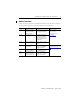
ControlNet-to-Foundation Fieldbus H1 Linking Device 3 Additional Information Refer to the following publications for additional information on the NI-FBUS Configurator, the 1788-CN2FF Linking Device, and general fieldbus solutions information. Pub Number Publication Title Scope Source AG-140 Wiring and Installation 31.25 kbit/s, Voltage Mode, Wire Medium Application Guide Overview of what you need to know to wire, power, and layout network components AG-163 31.
ControlNet-to-Foundation Fieldbus H1 Linking Device Important User Information Solid state equipment has operational characteristics differing from those of electromechanical equipment. Safety Guidelines for the Application, Installation and Maintenance of Solid State Controls (Publication SGI-1.1 available from your local Rockwell Automation sales office or online at http://www.ab.
ControlNet-to-Foundation Fieldbus H1 Linking Device ATTENTION 5 Environment and Enclosure This equipment is intended for use in a Pollution Degree 2 industrial environment, in overvoltage Category II applications (as defined in IEC publication 60664-1), at altitudes up to 2000 meters without derating. This equipment is considered Group 1, Class A industrial equipment according to IEC/CISPR Publication 11.
ControlNet-to-Foundation Fieldbus H1 Linking Device Handling the 1788-CN2FF Module ATTENTION Preventing Electrostatic Discharge This equipment is sensitive to electrostatic discharge, which can cause internal damage and affect normal operation. Follow these guidelines when you handle this equipment: • • • • • • Touch a grounded object to discharge potential static. Wear an approved grounding wriststrap. Do not touch connectors or pins on component boards.
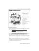
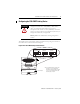
ControlNet-to-Foundation Fieldbus H1 Linking Device 7 1788-CN2FF Hardware Description Figure 1 ControlNet-to-Foundation Fieldbus Linking Device 1 2 3 1. ControlNet A and B BNC Connectors, to support single or redundant network topologies. 4 2. Case/Enclosure 9 3. ControlNet Network Status LEDs 1 4. Non-isolated ControlNet Network Access Port (NAP) 5. Power Supply Connector 10 6. DIN Rail Clip 7. ControlNet Module STATUS LED 8 8. Fieldbus Connectors 5 7 43163 6 9.
ControlNet-to-Foundation Fieldbus H1 Linking Device Power Conditioning You must use a power conditioner between your Fieldbus power supply and the Fieldbus network. You can use a power supply designed for Foundation Fieldbus operation which has the proper power conditioning elements. If you are using an ordinary power supply, a separate power conditioner must also be used.
ControlNet-to-Foundation Fieldbus H1 Linking Device 9 Configuring the 1788-CN2FF Linking Device ATTENTION The 1788-CN2FF module ships from the factory with configuration switches set to “ON (RESET)”. With switches “ON”, any configuration data would be reset on Power interruption. Set the switches to “OFF (NORMAL)” after initial power-up (to clean any Factory test configurations) but before you configure the module with your application. Remove power to the module before resetting configuration switches.
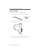
ControlNet-to-Foundation Fieldbus H1 Linking Device Installing the 1788-CN2FF The CN2FF has a rugged, simple clip for mounting reliably on a standard 35mm DIN rail. Follow these steps to mount the module onto a DIN rail. 1. Use a flat-bladed screwdriver to open the DIN Rail Clip to the unlocked position. Rail Clip Locked Rail Clip Unlocked 43167 2. Hook the lip on the rear of the module onto the top of a 35mm DIN rail and press the module down onto the DIN rail. DIN Rail Cover Press 43168 3.
ControlNet-to-Foundation Fieldbus H1 Linking Device 11 Figure 3 Install the 1788-CN2FF on to the DIN Rail DIN Rail Rail Clip Unlocked Position Device Along DIN Rail Rail Clip Locked 43169 Removing the 1788-CN2FF To remove a module, unlock it from the DIN rail by placing a screwdriver in the slot on the rail clip and opening the rail clip to the unlocked position as shown in step 1 on page 10. Then lift the device off of the rail.
ControlNet-to-Foundation Fieldbus H1 Linking Device Connecting Power The 1788-CN2FF requires 15-30V dc power and the cable is limited to a maximum of 3m in length. One power supply can support several CN2FFs. The power connector is a 6-pin screw terminal connector. The pinout for the power connector is shown in Figure 4. IMPORTANT Make sure that the power to the network is off when connecting the module.
ControlNet-to-Foundation Fieldbus H1 Linking Device 13 Connecting to the ControlNet Network There are two types of ControlNet connectors on the CN2FF, the BNC and the RJ-45. Using the BNC: • BNC connectors are for direct connection to a ControlNet network through a tap. • BNC connectors must be used to connect the CN2FF to the ControlNet network. Using the RJ-45: • The RJ-45 connector is a network access port (NAP).
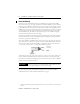
ControlNet-to-Foundation Fieldbus H1 Linking Device Setting the ControlNet Network Address Valid ControlNet network addresses are 1-99. Network address zero is reserved. Switch 1 controls the most significant decimal digit (the tens). Switch 2 controls the least significant decimal digit (the ones). Figure 6 shows the location of the network address switches and an example of switch settings for a network address of 15.
ControlNet-to-Foundation Fieldbus H1 Linking Device 15 Interpreting the LEDs: ControlNet Network Status The ControlNet network status LEDs are located on the front of the 1788-CN2FF, beside the ControlNet BNC connectors, as shown in Figure 1, Item 3. They indicate the state of the ControlNet connected to the BNC connectors. These LEDs do not reflect anything about the status of the network access port (NAP).
ControlNet-to-Foundation Fieldbus H1 Linking Device Interpreting the LEDs: Module Status The STATUS LED is located on the front of the 1788-CN2FF, between the two Fieldbus connectors, as shown in Figure 1, Item 7. It indicates whether the CN2FF is powered, configured, and operating properly. Table 8 shows how to interpret the STATUS LED states.
ControlNet-to-Foundation Fieldbus H1 Linking Device 17 Connecting to the Fieldbus Network Figure 9 Fieldbus Connector Locations on the 1788-CN2FF 43171 Fieldbus Connections Use pins 6 and 7 for the Fieldbus signals, as specified in the Fieldbus Standard for Use in Industrial Control Systems, Part 2, ISA-S50.02.1992. Refer to Figure 10 for the connector pinout of the 1788-CN2FF. IMPORTANT Make sure that the power to the network is off when connecting the module.
ControlNet-to-Foundation Fieldbus H1 Linking Device Device vs. Connection Clarifications This section describes the functional relationship and differences between 1788-CN2FF Connections and Foundation FieldbusΤΜ Devices. A connection does not always equal a device. ATTENTION The maximum number of “connections” is 30 per CN2FF. The recommended number of “devices” is 8 per H1 port on the CN2FF.
ControlNet-to-Foundation Fieldbus H1 Linking Device 19 1788-CN2FF Connections A connection is considered any link (wire connection) to a CNAI, CNAO, CNDI, and CNDO. When using the CNAO, refer to the graphic below that illustrates there are two connections for each CNAO. For help in determining the number of connections on a port, refer to the Device Info screen once you have downloaded the function block applications to the CN2FF.
ControlNet-to-Foundation Fieldbus H1 Linking Device To locate the Device Info, expand the CN2FF tree and double-click on Device Info. When accounting for the number of connections, you need to count the number of Tags in the FieldbusTag column and not the number identifying the Instances. Even though there is a duplicate Instance of 1, it is still counted as a separate FieldbusTag that counts against the total 30 connections. This example has 12 connections.
ControlNet-to-Foundation Fieldbus H1 Linking Device 21 1788-CN2FF and Foundation Fieldbus Devices Devices do not equate to connections. The current recommended number of devices per H1 port is 8 and the maximum number of devices per 1788-CN2FF module is 16 for any type of bus power used. ATTENTION The maximum number of “connections” is 30 per CN2FF. The recommended number of “devices” is 8 per H1 port on the CN2FF.
ControlNet-to-Foundation Fieldbus H1 Linking Device Specifications Type Specifications Operating Temperature 0 to 60°C (32 to 140°F) IEC 60068-2-1 (Test Ad, Operating Cold), IEC 60068-2-2 (Test Bd, Operating Dry Heat), IEC 60068-2-14 (Test Nb, Operating Thermal Shock) Storage Temperature –40 to 85°C (–40 to 185°F) IEC 60068-2-1 (Test Ab, Un-packaged Non-operating Cold), IEC 60068-2-2 (Test Bb, Un-packaged Non-operating Dry Heat), IEC 60068-2-14 (Test Na, Un-packaged Non-operating Thermal Shock) R
ControlNet-to-Foundation Fieldbus H1 Linking Device Type Specifications Indicators • Module Status • ControlNet Status, 1 each connection Connectors • • • • • Conductors 23 Wire Size Category Certifications (when product is marked) ControlNet - BNC connectors, provides redundancy two 10-position rotary switches Network Access Port - RJ45 (non-isolated) Fieldbus - 9-pin sub-D connectors Power Input Terminals: -Torque 5-7 in-lb.
Rockwell Automation Support Rockwell Automation provides technical information on the web to assist you in using our products. At http://support.rockwellautomation.com, you can find technical manuals, a knowledge base of FAQs, technical and application notes, sample code and links to software service packs, and a MySupport feature that you can customize to make the best use of these tools.