Allen-Bradley ControlNet-toFOUNDATION Fieldbus (Cat. No.
Important User Information Because of the variety of uses for the products described in this publication, those responsible for the application and use of this control equipment must satisfy themselves that all necessary steps have been taken to assure that each application and use meets all performance and safety requirements, including any applicable laws, regulations, codes and standards.
Table of Contents Introduction Product Overview . . . . . . . . . . . . . . . . . . . . . . . . . . . . . . . . . . . . . Closed-loop Control . . . . . . . . . . . . . . . . . . . . . . . . . . . . . . . . Configuration and Monitoring . . . . . . . . . . . . . . . . . . . . . . . . System Requirements . . . . . . . . . . . . . . . . . . . . . . . . . . . . . . . . . . Hardware . . . . . . . . . . . . . . . . . . . . . . . . . . . . . . . . . . . . . . . . Software . . . . . . . . . . . . . . . . . . . . .
ii Alarm Handling by the HMI. . . . . . . . . . . . . . . . . . . . . . . . . . . . Assembly Objects . . . . . . . . . . . . . . . . . . . . . . . . . . . . . . . . . . . . MAI Blocks. . . . . . . . . . . . . . . . . . . . . . . . . . . . . . . . . . . . . . MAO Blocks . . . . . . . . . . . . . . . . . . . . . . . . . . . . . . . . . . . . . MDI Blocks. . . . . . . . . . . . . . . . . . . . . . . . . . . . . . . . . . . . . . MDO Blocks . . . . . . . . . . . . . . . . . . . . . . . . . . . . . . . . . . .
Chapter 1 Introduction Product Overview The ControlNet-to-FOUNDATION Fieldbus linking device connects a ControlNet™ network with one or more FOUNDATION Fieldbus H1 (Fieldbus) networks. Each H1 network consists of multiple Fieldbus devices. Each field device has one or more function blocks. Each function block performs an elementary control function such as analog input, analog output, discrete input, or discrete output.
1-2 Introduction The linking device is similar to an I/O subsystem. An I/O subsystem typically contains several I/O modules. Each module has a number of channels. The channels perform one of these functions: • • • • analog input (AI) analog output (AO) discrete input (DI) discrete output (DO) The linking device models the I/O modules in software.
Introduction 1-3 The Fieldbus devices have View objects that are a collection of dynamic process data. Fieldbus devices broadcast alarms, collect trend data, and broadcast trend data. An HMI typically accesses the view objects, collects trends from different Fieldbus devices, processes alarms, and acknowledges alarms. The linking device permits a Fieldbus HMI on a PC connected to ControlNet to access and monitor Fieldbus devices as if the HMI were directly connected to the Fieldbus network.
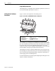
1-4 Introduction Compatibility Information The linking device is compatible with ControlNet specification version 1.03 (or later) and Fieldbus specification version 1.3. Linking Device Hardware Description Figure 1.2 shows the components of the linking device. Figure 1.
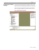
Introduction 1-5 NI-FBUS Configurator Software Use the NI-FBUS Fieldbus Configurator to configure a Fieldbus network and keep track of your configurations. The Configurator is an easy-to-use Description graphical environment for creating Fieldbus linkages, loops, and schedules. Figure 1.3 shows the Configurator Main window. For more information, refer to the NI-FBUS Configurator User Manual, publication 1788-6.5.2. Figure 1.3 NI-FBUS Configurator Main Window 1788-6.5.
1-6 Introduction Notes: 1788-6.5.
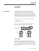
Chapter 2 Hardware Installation and Configuration Handling the Linking Device We recommend that you adhere to this precautionary information. ! Installing the Linking Device ATTENTION: This module contains ESD (Electrostatic Discharge) sensitive parts and assemblies. Static control precautions are required when installing or testing this assembly. Component damage may result if these procedures are not followed.
2-2 Hardware Installation and Configuration 3. Slide the linking device to the desired position on the DIN rail. After it is in position, push the rail snap into the locked position to lock it in place on the DIN rail.
Hardware Installation and Configuration 2-3 Connect the primary power supply to the center V and C pair. An optional backup power supply may be connected to the left V and C pair. The right V and C pair may be used to chain the primary power supply to other devices. All three terminals labeled C are connected in the linking device. The right two V terminals are connected in the linking device. These connections are indicated on the power connector by the lines over the V and C terminals.
2-4 Hardware Installation and Configuration Connecting to the Fieldbus Network The location of the Fieldbus connectors is shown in Figure 2.3. Figure 2.3 Fieldbus Connectors on the Linking Device Fieldbus Connectors If you want to make your own Fieldbus cable, make sure that it uses pins 6 and 7 for the Fieldbus signals, as specified in the Fieldbus Standard for Use in Industrial Control Systems, Part 2, ISA-S50.02.1992. Refer to Figure 2.4 for the connector pinout of the linking device. Figure 2.
Hardware Installation and Configuration Valid ControlNet network addresses are 1-99. Network address zero is reserved. Switch 1 controls the most significant decimal digit (the tens). Switch 2 controls the least significant decimal digit (the ones). Figure 2.5 shows the location of the network address switches and an example of switch settings for a network address of 15. Figure 2.
2-6 Hardware Installation and Configuration Follow these steps to set the ControlNet network address for the linking device. For optimum throughput, assign network addresses to your ControlNet nodes in a sequential order starting with 01 for the PC running the configuration software. 1. Choose and set a network address. 2. Write the network address setting in the space provided on the linking device label. 3. Apply (or cycle) power to the linking device to enable the new network address. 4.
Hardware Installation and Configuration 2-7 ControlNet Network Status LEDs The ControlNet network status LEDs are located on the front of the linking device, beside the ControlNet BNC connectors, as shown in Figure 1.2. They indicate the state of the ControlNet connected to the BNC connectors. These LEDs do not reflect anything about the status of the network if the linking device is connected to the network through the network access port (NAP).
2-8 Hardware Installation and Configuration Notes: 1788-6.5.
Chapter 3 Software Installation and Configuration After you have configured and installed the linking device, you are ready to Installing the NI-FBUS Configurator Software install the NI-FBUS Configurator software. Complete the following steps to install the NI-FBUS Configurator software: 1. Determine the ControlNet network address of the linking device or devices from rotary address switches. Refer to Figure 2.5. 2.
3-2 Software Installation and Configuration After installing the software components to the appropriate directories, the installer starts the NI-FBUS Interface Configuration Utility as shown in Figure 3.1. To reach this program after initial installation, click on the Windows Start icon, point to Programs, point to National Instruments FBUS, and select Interface Config. Figure 3.1 Interface Configuration Utility 1788-6.5.
Software Installation and Configuration 3-3 Configuring the Interface Address Configuring the NI-FBUS Configurator Software To add, view, or change the interface address of the linking device, complete the following steps: 1. In the NI-FBUS Interface Configuration Utility window, select the icon for the linking device you want to change and click on the Edit button. If you are adding a linking device, click on the Add Interface Device button. The Interface dialog box appears. 2.
3-4 Software Installation and Configuration 6. In the Path field, enter 02, the default path, indicating NI-FBUS uses the ControlNet port on an Allen-Bradley PC ControlNet interface card. The path is compromised of ASCII encoded hexadecimal bytes, separated by spaces, required to reach the destination linking device. 7. In the Timeout field, specify a timeout (in milliseconds) for communication with the linking device. The default value is most likely adequate.
Software Installation and Configuration 3-5 Installing Device Descriptions Device descriptions describe functionality of Fieldbus devices using the Fieldbus Device Description Language. Device Descriptions must be provided to NI-FBUS for all attached Fieldbus devices. NI-FBUS includes many standard DDs. Most devices contain custom functionality; therefore, you should install the DD for all attached Fieldbus devices.
3-6 Software Installation and Configuration Configuring Fieldbus Communication Parameters Each Fieldbus device must have a unique address within one Fieldbus network. It must also have a unique physical device tag. Each Fieldbus port of the linking device is considered a Fieldbus device. Therefore, each Fieldbus port must have its own address and tag. The linking device is shipped with all the Fieldbus ports set to the default address and without any physical device tag.
Software Installation and Configuration Testing the Installation 3-7 Make sure that you have installed and configured the RSLinx software and an Allen-Bradley PC ControlNet interface. The NI-FBUS Configurator requires these components to interact with the linking device. To make sure that your NI-FBUS software is correctly installed and is working properly, follow these steps: 1. Restart Windows NT. 2. Start the NI-FBUS Communications Manager by selecting the NIFB icon in the NI-FBUS menu.
3-8 Software Installation and Configuration Notes: 1788-6.5.
Chapter 4 Using the ControlNet-to-FOUNDATION Fieldbus H1 Linking Device This chapter describes: • the blocks in the linking device • configuring the linking device to access the AI, AO, DI, DO function blocks on the Fieldbus network from ControlNet • attributes of the created ControlNet objects, assembly objects, alarm handling • ControlNet connection details Blocks in the Linking Device The linking device is similar to an I/O subsystem. An I/O subsystem typically contains several I/O modules.
4-2 Using the ControlNet-to-FOUNDATION Fieldbus H1 Linking Device Analog Inputs This section describes configuration of the linking device to access any analog value (and status) in a Fieldbus device. It also describes the attributes of the created ControlNet analog input object. The linking device contains a number of MAI block instances. Each instance of the MAI block is the software equivalent of an analog input module in an I/O subsystem.
Using the ControlNet-to-FOUNDATION Fieldbus H1 Linking Device 4-3 The NI-FBUS Configurator sets up the analog input devices to publish their data on Fieldbus. The linking device MAI block subscribes to these values and produces them on ControlNet. Each MAI block has its own schedule of subscribing on Fieldbus and producing on ControlNet. For different rates (macrocycle) of production on ControlNet, you must choose different MAI blocks as shown in the Figure 4.2. Figure 4.
4-4 Using the ControlNet-to-FOUNDATION Fieldbus H1 Linking Device ControlNet Analog Input Objects The linking device creates an instance of a ControlNet AI object for every wired channel in the MAI block instances. Each instance of the ControlNet AI object has the attributes and access rules shown in Table 4.A. Table 4.A ControlNet Analog Input Object Attributes Attribute Number Name Type Access Initial Value Remarks 3 Value Float Get 0 4 CNStatus Boolean Get Bad ControlNet status.
Using the ControlNet-to-FOUNDATION Fieldbus H1 Linking Device 4-5 Figure 4.3 Alarm Attribute Definition Bit Position 7 6 5 4 3 2 1 0 Value X X X X X Acknowledge CLEARED ACTIVE Bits 7-3, DON’T CARE, are undefined when read and should be ignored when performing a GET. The DON’T CARE bits should be written as 0 when performing a SET. Bit 2, Acknowledge, is undefined when read and should be ignored when performing a GET.
4-6 Using the ControlNet-to-FOUNDATION Fieldbus H1 Linking Device The MAO function block has two valid configurations. In the first configuration the BKCAL_OUT parameter of the AO is not connected back to the controller. In this case, there is no mode handshake provided by the upstream controller for cascade initialization of the AO. You connect only the CN_OUT_Ax parameter from the MAO to the CAS_IN of the AO block as shown in Figure 4.4.
Using the ControlNet-to-FOUNDATION Fieldbus H1 Linking Device 4-7 Figure 4.5 Sample Cascaded AO Configuration The linking device consumes analog values produced by the controller on ControlNet and publishes these values on Fieldbus. The NI-FBUS Configurator sets up the analog output devices to subscribe to their data on Fieldbus. Each MAO block has its own schedule to consume data on ControlNet and publish it on Fieldbus.
4-8 Using the ControlNet-to-FOUNDATION Fieldbus H1 Linking Device That is, you may use channels CN_OUT_A3 and CN_OUT_A5 and not use any of the others. As shown in the lower loop of Figure 4.6, you can connect the MAO block to any parameter that is a float value and status combination. In other words, you can bring values from a PLC processor to any function block. The MAO block is not limited to interfacing with AO function blocks.
Using the ControlNet-to-FOUNDATION Fieldbus H1 Linking Device 4-9 The linking device contains a number of MDI block instances. Each instance of the MDI block is the software equivalent of a discrete input module in a I/O subsystem. Each MDI block has eight channels, with each channel containing a byte and a status pair.
4-10 Using the ControlNet-to-FOUNDATION Fieldbus H1 Linking Device ControlNet Discrete Input Objects The linking device creates an instance of a ControlNet DI object for every wired channel in the MDI block instances. Each instance of the ControlNet DI object has the attributes and access rules shown in Table 4.C. Table 4.C ControlNet Discrete Input Object Attributes Attribute Number Name Type Access Initial Value Remarks 3 Value Boolean Get 0 4 CNStatus Boolean Get Bad ControlNet status.
Using the ControlNet-to-FOUNDATION Fieldbus H1 Linking Device 4-11 Figure 4.8 Alarm Attribute Definition Bit Position 7 6 5 4 3 2 1 0 Value X X X X X Acknowledge CLEARED ACTIVE Bits 7-3, DON’T CARE, are undefined when read and should be ignored when performing a GET. The DON’T CARE bits should be written as 0 when performing a SET. Bit 2, Acknowledge, is undefined when read and should be ignored when performing a GET.
4-12 Using the ControlNet-to-FOUNDATION Fieldbus H1 Linking Device Discrete Outputs This section describes configuration of the linking device to control any discrete value (and status) in a Fieldbus device, such as in a Discrete Output (DO) function block. It also describes the attributes of the created ControlNet discrete output object. The linking device contains a number of MDO block instances. Each instance of the MDO block is the software equivalent of a discrete output module in a I/O subsystem.
Using the ControlNet-to-FOUNDATION Fieldbus H1 Linking Device 4-13 In the second configuration, shown in Figure 4.9, the controller provides the necessary mode handshake for cascade initialization of the DO block. In this case, you connect CN_OUT_Dx of the MDO block to the CAS_IN_D parameters of the DO block, and the BKCAL_OUT_D parameter of the DO block to BKCAL_INn of the MDO block.
4-14 Using the ControlNet-to-FOUNDATION Fieldbus H1 Linking Device Alarm Handling by the HMI The linking device makes the process alarms from AI and DI function blocks visible as attributes of the created ControlNet objects, as discussed in the previous sections. Fieldbus devices generate other types of alarms; for example, they send out an alarm whenever their static configuration changes. Other function block types also generate alarms.
Using the ControlNet-to-FOUNDATION Fieldbus H1 Linking Device 4-15 Table 4.E describes the attributes placed into the input and output assembly for each object type. Table 4.
4-16 Using the ControlNet-to-FOUNDATION Fieldbus H1 Linking Device MDI Blocks For each MDI block configured in the linking device beginning with the lowest numbered module, each channel that is connected to a Fieldbus function block has attributes 3, 4, and 150 placed into the required input assembly object. Each MDI requires 4 bytes in the input assembly object.
Using the ControlNet-to-FOUNDATION Fieldbus H1 Linking Device 4-17 Figure 4.11 Sample NI-FBUS Configurator View of ControlNet Object Information Changing the Linking Device Configuration Once a configuration is created in the linking device and a PLC processor or PC is using the offsets previously defined, an addition to the configuration should not require you to change functioning code in your application.
4-18 Using the ControlNet-to-FOUNDATION Fieldbus H1 Linking Device Because existing programs may be using a configuration, the deletion of a linkage from a Fieldbus network does not result in a renumbering of ControlNet objects or a reordering of the assembly object offsets. If the Fieldbus device is no longer present, Fieldbus and ControlNet status indicates an error condition, and the object and assembly offset resources continue to be in use.
Appendix A Specifications Table A.
A-2 Specifications Compliance to European Union Directives If this product has the marking, it is approved for installation within the European Union and EEA regions. It has been designed and tested to meet the following directives.
Specifications A-3 Hazardous Location Approval This product may be certified for general use as well as for use in hazardous locations. Actual agency certification is indicated by the product label as shown below, and not by statements in any user documentation. Example of the certification product label: CL I, DIV 2 GP A,B,C,D TEMP To comply with certification for use in hazardous locations, the following information becomes a part of the product literature for this certified industrial control product.
A-4 Specifications Approbation d’utilisation en environnements dangereux Ce produit est certifié pour une utilisation générale aussi bien que pour une utilisation en environnements dangereux. La certification en vigueur est indiquée par l'étiquette produit et non par des indications dans la documentation utilisateur.
Glossary We use these abbreviations, acronmys, and initialisms throughout the document. AI Analog Input AO Analog Output CH Channel DD Device Description DI Discrete Input DO Discrete Output Fieldbus FOUNDATION Fieldbus H1 H1 31.25 Kbps Fieldbus HMI Human-Machine Interface MAI Multiple Analog Input MAO Multiple Analog Output MDI Multiple Discrete Input MDO Multiple Discrete Output PID Proportional Integral Derivative PLC Programmable Logic Controller 1788-6.5.
G-2 Notes: 1788-6.5.
Index Numerics 11-30V dc power supply 2-2 1784-KTCX15 1-3 1784-PCC 1-3 A Alarm Handling by the HMI 4-14 Alarm Handling for Analog Inputs 4-4 Alarm Handling for Discrete Inputs 4-10 Analog Inputs 4-2 Analog Outputs 4-5 Assembly Objects 4-14 Attributes in Input and Output Assemblies 4-15 ControlNet Discrete Output Object Attributes 4-13 ControlNet Discrete Output Objects 4-13 ControlNet Network Address Switches Set to 15 2-5 ControlNet Network Status LEDs 2-7 custom function blocks 1-2 D Description of Con
I-2 Index M MAI Blocks 4-15 MAO Blocks 4-15 MDI Blocks 4-16 MDO Blocks 4-16 Module STATUS LED 2-6 T Testing the Installation 3-7 Trends and Alarms 4-18 Typical Linking Device Connections to a ControlNet Network 2-3 U N network access port (NAP) 2-3 NI-FBUS Configurator version 2.
Allen-Bradley Publication Problem Report If you find a problem with our documentation, please complete and return this form. Pub. Name ControlNet-to-Foundation Fieldbus H1 Linking Device User Manual Cat. No. 1788-CN2FF Check Problem(s) Type: Pub. No. 1788-6.5.1 Pub. Date January 1999 Part No.
PLEASE FASTEN HERE (DO NOT STAPLE) PLEASE FOLD HERE NO POSTAGE NECESSARY IF MAILED IN THE UNITED STATES BUSINESS REPLY MAIL FIRST-CLASS MAIL PERMIT NO.
Publication 1788-6.5.1 - January 1999 PN 955133-78 ©1999 Rockwell International Corporation. Printed in the U.S.A.