Installation Instructions ControlNet-to-DeviceNet Linking Device Catalog Number 1788-CN2DN Topic Page Important User Information 2 About the CN2DN Linking Device 7 Parts List 8 Required System Components 9 Install the CN2DN Device 9 Mount the CN2DN Device on a DIN Rail 10 Mount the CN2DN Device on a Panel or Other Fixture 12 Wire a Power Supply to the CN2DN Device 13 Set the Node Addresses and Communication Rate 15 Connect the CN2DN Device to a ControlNet Network 16 Connect the CN2DN
ControlNet-to-DeviceNet Linking Device Important User Information Solid state equipment has operational characteristics differing from those of electromechanical equipment. Safety Guidelines for the Application, Installation and Maintenance of Solid State Controls (publication SGI-1.1 available from your local Rockwell Automation sales office or online at http://literature.rockwellautomation.com) describes some important differences between solid state equipment and hard-wired electromechanical devices.
ControlNet-to-DeviceNet Linking Device 3 North American Hazardous Location Approval The following Information applies when operating this equipment in hazardous locations: Informations sur l'utilisation de cet équipement en environnements dangereux: Products marked "CL I, DIV 2, GP A, B, C, D" are suitable for use in Class I Division 2 Groups A, B, C, D, Hazardous Locations and nonhazardous locations only.
ControlNet-to-DeviceNet Linking Device European Hazardous Location Approval European Zone 2 Certification (The following applies when the product bears the EEx Marking) This equipment is intended for use in potentially explosive atmospheres as defined by European Union Directive 94/9/EC.
ControlNet-to-DeviceNet Linking Device 5 Environment and Enclosure ATTENTION This equipment is intended for use in a Pollution Degree 2 industrial environment, in overvoltage Category II applications (as defined in IEC publication 60664-1), at altitudes up to 2000 m (1.24 mi) without derating. This equipment is considered Group 1, Class A industrial equipment according to IEC/CISPR Publication 11.
ControlNet-to-DeviceNet Linking Device Prevent Electrostatic Discharge ATTENTION This equipment is sensitive to electrostatic discharge, which can cause internal damage and affect normal operation. Follow these guidelines when you handle this equipment: • Touch a grounded object to discharge potential static. • Wear an approved grounding wriststrap. • Do not touch connectors or pins on component boards. • Do not touch circuit components inside the equipment.
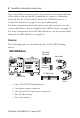
ControlNet-to-DeviceNet Linking Device 7 About the CN2DN Linking Device Use following graphic to identify the components of your ControlNet-to-DeviceNet linking device. CN2DN Linking Device Components Power Port and Connector DeviceNet Node Address Switches DeviceNet Port and Connector LED Indicators DeviceNet Baud Rate Switch Network Access Port ControlNet Connection Ports ControlNet Node Address Switches The DeviceNet connection port is located on the top left corner of the device.
ControlNet-to-DeviceNet Linking Device Two ControlNet connection ports are located on the bottom left side of the device and provide the availability to connect a redundant network. See the section titled Connect the CN2DN Device to a ControlNet Network on page 16 for more information. For more information about the power port and connector, see the section titled Wire a Power Supply to the CN2DN Device on page 13.
ControlNet-to-DeviceNet Linking Device 9 Required System Components In order to install your 1788-CN2DN device, you will need the following system components. • A 24V dc power supply and • A securely installed zinc-plated, yellow-chrome steel, DIN rail, panel, or other suitable fixture. Install the CN2DN Device Complete the following tasks to install the CN2DN Linking Device.
ControlNet-to-DeviceNet Linking Device Mount the CN2DN Device on a DIN Rail ATTENTION IMPORTANT This product is grounded through the DIN rail to chassis ground. Use zinc plated yellow-chromate steel DIN rail to assure proper grounding. The use of other DIN rail materials (for example, aluminum and plastic) that can corrode, oxidize, or are poor conductors, can result in improper or intermittent grounding. Secure DIN rail to mounting surface approximately every 200 mm (7.87 in.
ControlNet-to-DeviceNet Linking Device 11 3. Clip each of the end anchors onto the DIN rail next to the CN2DN device. End Anchor onto DIN Rail DIN Rail Clip On End Anchors Next to Device Grounded DIN Rail Slide the Anchor Against the CN2DN Device Tighten the Clamping Screws 4. Slide each anchor against the device and tighten the screws on the front of the end anchor.
ControlNet-to-DeviceNet Linking Device 5. If you are mounting your CN2DN device in a high-vibration area, insert screws (not included) into the holes of the mounting tabs and tighten so that the screws are firmly anchored into the panel behind the device. Mount Tabs (Optional Use) Ground Connection (Optional) - For use if DIN rail or panel is not grounded. If used, this tab must be properly connected to the earth ground.
ControlNet-to-DeviceNet Linking Device 13 Wire a Power Supply to the CN2DN Device ATTENTION To comply with the CE Low Voltage Directive (LVD), power to this equipment and DeviceNet must be powered from a source compliant with the following: Safety Extra Low Voltage (SELV) or Protected Extra Low Voltage (PELV). To comply with UL restrictions, DeviceNet must be powered from a source compliant with the following: Class 2 or Limited Voltage/Current.
ControlNet-to-DeviceNet Linking Device 3. Loosen the two left-most terminal screws of the power connector. IMPORTANT Do not connect more than two wires to any terminal. 4. Insert the bare power supply wire ends into the left-side terminals of the power supply connector using the diagram as a guide. 5. Tighten the two left terminal screws using 0.6 Nm (7 in-lb) torque.
ControlNet-to-DeviceNet Linking Device 15 Set the Node Addresses and Communication Rate Complete the following steps to set the node addresses using the switches on the front of the CN2DN device. CN2DN Device Switches DeviceNet Address Switches DeviceNet Baud Rate Switch ControlNet Address Switches 1. To set the DeviceNet node address, use a small flat-head screwdriver to turn the arrows of the switches towards the desired node numbers. DeviceNet switches shown set to node 14.
ControlNet-to-DeviceNet Linking Device Connect the CN2DN Device to a ControlNet Network Complete the following steps to connect your CN2DN linking device to the ControlNet network. WARNING If you connect or disconnect the communications cable with power applied to this module or any device on the network, an electrical arc can occur. This could cause an explosion in hazardous location installations. 1. Attach the BNC connector of the ControlNet cable to ControlNet port A.
ControlNet-to-DeviceNet Linking Device 17 Connect the CN2DN Device to a DeviceNet Network WARNING If you connect or disconnect the communications cable with power applied to this module or any device on the network, an electrical arc can occur. This could cause an explosion in hazardous location installations. Complete the following steps to connect your CN2DN device to a DeviceNet network using the 10-pin linear connector included with the CN2DN device.
ControlNet-to-DeviceNet Linking Device 2. Wrap the end of the cable with 38 mm (1.5 in.) of shrink wrap, covering part of the exposed conductors and part of the trunk line insulation. Jacket 38 mm (1.5 in.) Shrink Wrap 41841 3. Strip 8.1 mm (0.32 in.) of the insulation from the end of each of the colored insulated conductors. Jacket Shrink Wrap 8.1 mm (0.32 in.) 41842 4. Insert each colored conductor into the matching color-coded terminal cavity of the open-style connector. 5.
ControlNet-to-DeviceNet Linking Device 19 The resistor should bridge the blue and white terminal cavities. 121 Ω Resistor Black Red White Blue Bare or Shield 41827 6. Tighten all of the terminal screws using 0.6 Nm (7 in-lb) torque. You have completed connecting to the DeviceNet network. Uninstall the CN2DN Linking Device Complete the following steps to uninstall the CN2DN linking device. 1. Remove power from the CN2DN device. 2. Disconnect the power, DeviceNet, and ControlNet connectors. 3.
ControlNet-to-DeviceNet Linking Device 4. To remove the CN2DN linking device from the DIN rail, pull down on the two latches at the bottom of the device while pulling the CN2DN device away from the DIN rail. Pull down on DIN rail latches. You may need to insert a flat-head screwdriver between the DIN rail latch and the tab that locks the latch into place in order to remove the device.
ControlNet-to-DeviceNet Linking Device 21 Interpret the LED Indicators Use the LED indicators on the CN2DN linking device to monitor the following: • • • • Module Status Linking Activity Status DeviceNet Network Status ControlNet Network Status CN2DN Device LED Indicators DeviceNet Network Status Indicators Module Status and Linking Activity Status Indicators ControlNet Status Indicators Publication 1788-IN052D-EN-P - February 2007
ControlNet-to-DeviceNet Linking Device Module Status Use the following table to interpret your Module Status LED indicators and determine if corrective action is necessary. Module Status Indicator LED Indicator Device Status Off No power to device. Recommended Action A. Verify that the power supply is functioning properly. B. Cycle power supply. C. Remove power and check input power wiring. Reapply power. D. Replace the CN2DN linking device.
ControlNet-to-DeviceNet Linking Device 23 Module Status Indicator LED Indicator Device Status Recommended Action Green, flashing The CN2DN device is functioning but not communicating with devices. Use RSNetworx software to configure the CN2DN device. See Additional Resources for publications with more information about configuring the CN2DN device. Green, steady Fully operational. The None.
ControlNet-to-DeviceNet Linking Device Linking Activity Status The Linking Activity LED indicator displays the status of communication between the DeviceNet and ControlNet networks as well as the amount of traffic. Use the following table to interpret the Linking Activity LED indicator. Linking Activity LED Indicator LED Indicator Linking Activity Status Off No network traffic is occurring between the ControlNet to DeviceNet networks. I/O traffic may be present.
ControlNet-to-DeviceNet Linking Device 25 ControlNet Network Status The CNet A and CNet B LED indicators display the status of the ControlNet network and individual channels. The ControlNet network may recognize more than one network status a time. If more than one status is present, the CN2DN linking device will display the highest priority status. Use the following table to interpret the ControlNet LED indicators.
ControlNet-to-DeviceNet Linking Device DeviceNet Network Status The DeviceNet network indicators, DNet Network Status and DNet I/O Status, indicate the state of the DeviceNet network and the state of DeviceNet I/O modules. Use the following tables to interpret your DeviceNet LED indicators located at the top right corner of the CN2DN device. DNet Network Status Indicator LED Indicator DeviceNet Network Status Recommended Action Off No DeviceNet connection.
ControlNet-to-DeviceNet Linking Device 27 DNet Network Status Indicator LED Indicator DeviceNet Network Status Recommended Action Green, steady One or more devices connected and communicating. None needed. Red, flashing One or more connections timed-out. Use programming software to view tags specific to the devices in order to troubleshoot the DeviceNet network.
ControlNet-to-DeviceNet Linking Device DNet I/O Status Indicator LED Indicator I/O Device Status Off No connection to device. Recommended Action A. Verify that the DeviceNet network is powered. B. Verify the connected device is functioning properly. Green, flashing Device is in program mode (idle). To put the device in run mode, use programming software. Green, steady Device is in run mode. To put the device in program mode, use programming software.
ControlNet-to-DeviceNet Linking Device 29 Troubleshoot the DeviceNet Network If DeviceNet network communications fail, you need to complete one or both of these tasks to troubleshoot the DeviceNet network. • View and interpret DeviceNet network status codes. • View and interpret the controller status tags using RSLogix5000 software. View and Interpret DeviceNet Status Codes on the DeviceNet Scanner In order to view the DeviceNet status code, locate the scanner on the DeviceNet network.
ControlNet-to-DeviceNet Linking Device DeviceNet Status Codes Status Code Description of Status Recommended Action 70 The address of the device is already in use by another device on the network. The scanner failed the duplicate node address check. Change the address of the device to an unused address. 71 Invalid data in scan list. Use RSNetworx software to reconfigure the scan list. 72 Slave device stopped communicating.
ControlNet-to-DeviceNet Linking Device 31 DeviceNet Status Codes Status Code 75 Description of Status Recommended Action Either or both of the following: Verify that the device has: • The device does not have a scan list. • a configured scan list. • The device has not received communication from any other device. • a properly-wired connection to the network 76 No direct network traffic for scanner. The scanner hears other network communication but does not hear any directed to it. None.
ControlNet-to-DeviceNet Linking Device DeviceNet Status Codes Status Code 78 Description of Status Device is configured in scan list, but not communicating. It has failed to communicate during the scanner’s second scan, which followed the display of status error code 72. Recommended Action • Verify device’s: – power. – communication connections. • If the device is polled, make sure the interscan delay is long enough for the device to return its data.
ControlNet-to-DeviceNet Linking Device 33 DeviceNet Status Codes Status Code Description of Status Recommended Action 80 Scanner is in idle mode. If desired, put network in run mode by completing the following steps. 1. Put the controller in run or remote run mode using the keyswitch on the controller or through RSLogix5000 software. 2. Turn on the bit O.CommandRegister.Run for the scanner. 81 Controller has set the scanner to the faulted mode.
ControlNet-to-DeviceNet Linking Device DeviceNet Status Codes Status Code 83 Description of Status Device returns error responses when the scanner attempts to communicate with it. Recommended Action • Use RSNetWorx software to: – check the accuracy of the scan list. – check the configuration of the device. The device may be in another scanner’s scan list. • Use the slave device’s documentation to verify that the device supports the message type used by the scanner.
ControlNet-to-DeviceNet Linking Device 35 DeviceNet Status Codes Status Code Description of Status Recommended Action The device is in idle mode, or not producing data, while the scanner is in run mode. • Check the configuration and status of the device. Scanner cannot listen to shared inputs from slave device because the owning scanner has not established communication with that slave device. • Verify primary scanner connection and configuration.
ControlNet-to-DeviceNet Linking Device DeviceNet Status Codes Status Code 91 Description of Status Bus-off condition likely due to cable or signal errors. Recommended Action • Cycle power to the device. • Verify that all devices are set to the same baud rate. • Check DeviceNet cabling to make sure no short circuits exist between CAN (blue and white) wires and power or shield (black, red, and shield) wires.
ControlNet-to-DeviceNet Linking Device 37 DeviceNet Status Codes Status Code Description of Status Recommended Action 96 Communication port is in test mode. None. 97 The controller has placed the scanner in halt mode.February If the O.CommandRegister.HaltScanner bit is on, turn it off then cycle scanner power. 98 General firmware error. Replace device. 99 System Failure. Replace device.
ControlNet-to-DeviceNet Linking Device 3. Determine which tags you need to view using the following procedure. a. Determine the first part of the tag title specific to your device using the table below.
ControlNet-to-DeviceNet Linking Device 39 4. Scroll through the list of tags to locate the specific tag you need. Use the following examples as references when determining which tags to view. 1756-DNB Tag Title Example Tag Titled Local:3:I:StausRegister used to troubleshoot a problem specific to the DeviceNet module or network. Tag Titled Local:3:S used to troubleshoot a problem specific to a device connected to the DeviceNet network. Tag Titled Local:3:O.
ControlNet-to-DeviceNet Linking Device 1788-CN2DN Tag Title Example Tag Titled As_You_Name:I:StausRegister used to troubleshoot a problem specific to the DeviceNet module or network. Tag Titled As_You_Name:S used to troubleshoot a problem specific to a device connected to the DeviceNet network. Tag Titled As_You_Name:O.
ControlNet-to-DeviceNet Linking Device 41 5. If need to troubleshoot Status Register tags, use the following table as a reference to interpret module or network status. Status Register Tag Values If Tag Member Displays Value Then Status Is Run 0 Scanner in idle mode. Run 1 Scanner in run mode. Fault 0 Scanner not faulted. Fault 1 Scanner faulted. DisableNetwork 0 Scanner not disabled. DisableNetwork 1 Scanner disabled. DeviceFailure 0 Scanner communicating with all devices.
ControlNet-to-DeviceNet Linking Device 6. If you need to troubleshoot Status Tags (:S), use the following table as a reference to interpret device status. If You Want Information About Then See Member Data Type I/O scans count. ScanCounter DINT Indication that a device is not communicating on the network. DeviceFailureRegister SINT[8] AutoverifyFailureRegister SINT[8] Use the following information to interpret status: • There is 1 bit for each address on the DeviceNet network (0 -63).
ControlNet-to-DeviceNet Linking Device 43 If You Want Information About Then See Member Data Type DeviceIdleRegister SINT[8] ActiveNodeRegister SINT[8] ASCII representation of scanner status/display. StatusDisplay SINT[4] Address of the scanner. ScannerAddress SINT Status code of scanner. ScannerStatus SINT Indication that a device is idle. Use the following information to interpret status: • There is 1 bit for each address on the DeviceNet network (0 -63).
ControlNet-to-DeviceNet Linking Device If You Want Information About Address with an error. Then See Member Data Type ScrollingDeviceAddress SINT ScrollingDeviceStatus SINT DeviceStatus SINT[64] Use the following information to interpret status: • Scrolls through the addresses with errors. • ScrollingDeviceStatus member shows the status code. A status code of an address with an error. Use the following information to interpret status: • Scrolls through addresses with errors.
ControlNet-to-DeviceNet Linking Device 45 7. If you need to troubleshoot the CommandRegister tags, use the following table to interpret or change the status associated with the data bit.
ControlNet-to-DeviceNet Linking Device Troubleshoot the ControlNet Network If ControlNet network communications fail, you need to complete one or more of the following tasks to troubleshoot the ControlNet network. • Interpret the LED Indicators of ControlNet devices on the network. • View and interpret the status indicators displayed on the ControlNet network devices. • Check ControlNet network for media problems.
ControlNet-to-DeviceNet Linking Device 47 Specifications CN2DN Linking Device, 1788-CN2DN Attribute Value Dimensions (H x W x D), Approx. 120 x 200 x 87 mm (4 11/16 x 7 7/8 x 3 7/16 in.) Enclosure Type None (Open-style) IEC Temp Code T4 Isolation Voltage 30V, Basic Insulation Type Tested at 720V dc for 60 seconds, between all ports North American Temp Code T4A Wiring Category(1) 3 - on power ports 2 - on communication ports Wire Size, Power 2.5 mm2 (14 AWG)… 0.
ControlNet-to-DeviceNet Linking Device Environmental Specifications Attribute Value Conducted RF Immunity IEC 61000-4-6: 10V rms with 1 kHz sine-wave 80% AM from 150 kHz…80 MHz EFT/B Immunity IEC 61000-4-4: ±4 kV at 2.5 kHz on power ports ±2 kV at 5 kHz on communications ports Emissions CISPR 11: Group 1, Class A ESD Immunity IEC 61000-4-2: 6 kV contact discharges 8 kV air discharges Radiated RF Immunity IEC 61000-4-3: 10V/m with 1 KHz sine-wave 80% AM from 30...
ControlNet-to-DeviceNet Linking Device 49 Environmental Specifications Attribute Value Temperature, Operating IEC 60068-2-1 (Test Ad, Operating Cold), IEC 60068-2-2 (Test Bd, Operating Dry Heat), IEC 60068-2-14 (Test Nb, Operating Thermal Shock): 0…60 °C (32…140 °F) Temperature, Storage IEC 60068-2-1 (Test Ab, Unpackaged Non-operating Cold), IEC 60068-2-2 (Test Bb, Unpackaged Non-operating Dry Heat), IEC 60068-2-14 (Test Na, Unpackaged Non-operating Thermal Shock): -40...85 °C (-40...
ControlNet-to-DeviceNet Linking Device Certifications The following certifications apply when the product is marked. Certification(1) Value C-Tick Australian Radiocommunications Act, compliant with: AS/NZS CISPR 11; Industrial Emissions c-UL-us UL Listed Industrial Control Equipment, certified for US and Canada. See UL File E65584. UL Listed for Class I, Division 2 Group A,B,C,D Hazardous Locations, certified for U.S. and Canada.
ControlNet-to-DeviceNet Linking Device 51 Additional Resources Use the following table to determine which publication best suits your information needs. Topic Publication Title Publication No. Programming, configuring, using, and troubleshooting of ControlNet modules. ControlNet Modules in Logix5000 Control Systems CNET-UM001 Planning and installating a ControlNet network. ControlNet Coax Media Planning and Installation Guide CNET-IN002 Planning and installating a DeviceNet network.
Rockwell Automation Support Rockwell Automation provides technical information on the web to assist you in using its products. At http://support.rockwellautomation.com, you can find technical manuals, a knowledge base of FAQs, technical and application notes, sample code and links to software service packs, and a MySupport feature that you can customize to make the best use of these tools.