
Installation Guide Manual

42 Rockwell Automation Publication CNET-IN001C-EN-P - October 2011
Chapter 2 Topology and Signal Considerations
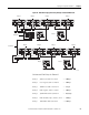
Delay 8 Fiber modules; 94 ns + 901 ns = 0.995 μs
Delay 9 20 m coax cable x 4.17 ns/m = 0.083 μs
Total delay for Channel A = 28.57 μs
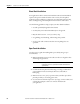
Calculate and Total the Delays for Channel B
Delay 1 750 m coax cable x 4.17 ns/m = 3.127 μs
Delay 2 Coax repeater; 901 ns + 100 ns = 1.001 μs
Delay 3 1000 m coax cable x 4.17 ns/m = 4.17 μs
Delay 4 Fiber repeater; 901 ns + 153 ns = 1.054 μs
Delay 5 3200 m fiber cable x 5.01 ns/m = 16.032 μs
Delay 6 Fiber modules; 153 + 901 ns + 94 ns = 1.148 μs
Delay 7 100 m fiber cable x 5.01 ns/m = 0.501 μs
Delay 8 Fiber modules; 94 ns + 901 ns = 0.995 μs
Delay 9 20 m coax cable x 4.17 ns/m = 0.083 μs
Total delay for Channel B = 28.11 μs
Skew between channels =
(Delay through A) – (delay through B) = 28.57 μs – 28.11 μs = 0.46 μs
This is a valid network because the calculated skew of 0.46 μs is less than the
maximum allowable skew of 1.6 μs.