
Installation Guide Manual

Rockwell Automation Publication CNET-IN001C-EN-P - October 2011 41
Topology and Signal Considerations Chapter 2
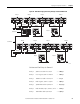
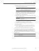
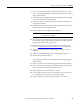
Figure 14 - Maximum Propagation Delay Through a Redundant Network
Calculate and Total Delays for Channel A
Delay 1 500 m coax cable x 4.17 ns/m = 2.085 μs
Delay 2 Coax repeater; 901 ns + 100 ns = 1.001 μs
Delay 3 1000 m coax cable x 4.17 ns/m = 4.17 μs
Delay 4 Fiber repeater; 901 ns + 153 ns = 1.054 μs
Delay 5 3500 m fiber cable x 5.01 ns/m = 17.535 μs
Delay 6 Fiber modules; 153 + 901 ns + 94 ns = 1.148 μs
Delay 7 100 m fiber cable x 5.01 ns/m = 0.501 μs
31417-M
Delay 2 Delay 4 Delay 6 Delay 8
Delay 1
Delay 3
Delay 5 Delay 7
500 m
1000 m
3500 m 100 m
20 m
20 m
Node 1
Node 3
Node 2
Delay 2 Delay 4 Delay 6 Delay 8
Delay 1 Delay 3
Delay 5 Delay 7
750 m 1000 m
3200 m 100 m
Node 3 Node 2
Delay 9
Delay 9
20 m 20 m
Channel A
Channel B