
Installation Guide User Manual

Publication CNET-IN002B-EN-P - June 2010 33
Plan a ControlNet Coax Media System Chapter 2
Follow these installation guidelines:
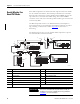
• Install the cable system so that the trunk cables at any physical node
location can be easily identified and labeled with the appropriate icon or
letter. Each redundant ControlNet node is labeled so you can connect it
to the corresponding trunk cable.
• Avoid connecting a single node’s redundant trunk-cable connections on
different segments; this causes erratic operation.
• Install the redundant cable such that the path on both channels is similar
in length, node order, and nodes connected.
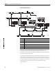
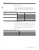
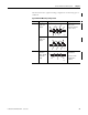
Follow the charts for series A repeaters for the total difference in length
between the two trunk cables of a redundant-cable link, which decreases
as the number of repeaters increases. If you are using series B repeaters,
you are allowed to have a total skew of 1.6 µs between channels.
Allowable Cable Length Difference vs. Repeaters in Series
for Coax Media
0
1
2
3
4
5
6
0 50 100 150 200 250 300 350 400 450
Allowable Coax Cable Length Difference (meters)
Repeaters in
Series
Wors t Case
Typic al Case
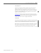
Allowable Cable Length Difference vs. Repeaters in Series
for Fiber Media
0
1
2
3
4
5
6
0 50 100 150 200 250 300 35 0 400 450
Allowable Fiber Cable Length Difference (meters)
Repeaters in
Series
Wors t Case
Ty pical Case
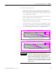
IMPORTANT
For redundant cabling to function properly, the data
transmission skew between channel A and channel B must be
1.6 µs or less. Skew is defined as the signal delay difference
between channel A and channel B. To keep the skew at a
minimum, you must keep all lengths of fiber and coax as similar
as possible. You must also design the cable paths such that the
signal passes through the same number and types of repeaters
on both channels.