ControlNet Coax Media Planning and Installation Guide Catalog Number 1786-series Installation Instructions
Important User Information Solid state equipment has operational characteristics differing from those of electromechanical equipment. Safety Guidelines for the Application, Installation and Maintenance of Solid State Controls (publication SGI-1.1 available from your local Rockwell Automation sales office or online at http://www.rockwellautomation.com/literature/) describes some important differences between solid state equipment and hard-wired electromechanical devices.
Summary of Changes Introduction This release of this document contains updated information and illustrations. New information is marked by change bars in the side column, as shown to the right. New Information 3Publication CNET-IN002B-EN-P - June 2010 See the table for the section that contains the information. Section Changes Chapter 1 Updated illustrations that show how components configure a cable system. Chapter 2 Equation for determining a segment with an attenuation value.
Summary of Changes Notes: 4 Publication CNET-IN002B-EN-P - June 2010
Table of Contents Preface Introduction . . . . . . . . . . . . . . . . . . . . . . . . . . . . . . . . . . . . . . . . . . . . . . . 7 Who Should Use This Manual. . . . . . . . . . . . . . . . . . . . . . . . . . . . . . . . . 7 Additional Resources . . . . . . . . . . . . . . . . . . . . . . . . . . . . . . . . . . . . . . . . 7 Chapter 1 ControlNet Cable System Overview Introduction . . . . . . . . . . . . . . . . . . . . . . . . . . . . . . . . . . . . . . . . . . . . . . . 9 Basic Cable Terminology .
Table of Contents Appendix A Mounting Dimensions Introduction . . . . . . . . . . . . . . . . . . . . . . . . . . . . . . . . . . . . . . . . . . . . . . 65 Taps. . . . . . . . . . . . . . . . . . . . . . . . . . . . . . . . . . . . . . . . . . . . . . . . . . . . . 65 Universal Mounting Bracket . . . . . . . . . . . . . . . . . . . . . . . . . . . . . . . . . 66 Transition Plate . . . . . . . . . . . . . . . . . . . . . . . . . . . . . . . . . . . . . . . . . . .
Preface Introduction This manual describes the required components of a ControlNet coax media system. The information is useful in determining your system and for installing the required components. Who Should Use This Manual You must have an understanding of the fundamentals of electronics and electrical codes to use the procedures in this document. If you need additional information, refer to the related documentation listed below.
Preface Notes: 8 Publication CNET-IN002B-EN-P - June 2010
Chapter 1 ControlNet Cable System Overview Introduction The ControlNet cable system gives you the flexibility to design a communication network for your particular application. This chapter provides an overview of the parts comprising the network so you have a better understanding of how to configure your application. We strongly recommend that you spend sufficient time on planning your network installation requirements before assembling any of the hardware.
Chapter 1 ControlNet Cable System Overview Basic Cable Terminology Item Term The table defines some of the basic ControlNet network terminology. Description Item Trunk line The trunk cable is the bus or central part of a cable system, with a trunk-cable section being a length of cable between any two taps. Each node is connected to the trunk cable with a tap. Bridge A device that provides a communication connection between networks.
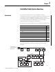
ControlNet Cable System Overview Elements Comprising the Coax Media System Chapter 1 The ControlNet coax media system consists of components, such as the trunk, drop cables, taps, cable connectors, terminating resistors, nodes, and repeaters to create segments, links, and bridges for network communication. For information on purchasing components, see the ControlNet Media System Component List, publication AG-PA002.
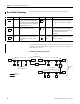
Chapter 1 ControlNet Cable System Overview Taps are available with the following connector configurations. • T or Y placement of BNC connectors (IP20) T-tap Y-tap • T placement of TNC connector (IP67) T-tap • Straight or right-angle connector on the drop cable Straight Right-angle Trunk Cable and Connectors The trunk cable (catalog number 1786-RG6) is a low-loss, RG-6 quad-shield coaxial cable. It’s the bus or central part of the coax media system.
ControlNet Cable System Overview Chapter 1 Trunk Line Terminating Resistors A 75 Ω terminating resistor must be installed on the tap at each end of a trunk-cable section. Terminating resistors absorb the electrical energy of the signal at the ends of the cable to prevent reflections, which interfere with signals that are being sent. Two types of terminating resistors are available depending on the connectors and taps that are being used on a trunk line.
Chapter 1 ControlNet Cable System Overview Repeater When you insert a repeater into the cable system, a new segment is created. The same restrictions on the number of taps and cable length apply to this new segment, as explained on page 13. Segment A TR Segment B T T T N N N T TR TR R T T T T N N N TR Trunk Line Drop Line 44989 IMPORTANT A repeater counts as a device on a segment but does not require a node address.
ControlNet Cable System Overview Chapter 1 Link A link is a collection of one or more segments connected together by repeaters. Each node in a link must have a unique address, ranging from 1…99, to function on the network. Link Segment A TR Segment B T T T N N N TR T TR T R T T T N N N TR Trunk Line Drop Line 44990 Bridge A bridge is a device that acts as a communication connection between networks.
Chapter 1 ControlNet Cable System Overview Notes: 16 Publication CNET-IN002B-EN-P - June 2010
Chapter 2 Plan a ControlNet Coax Media System Introduction The information in this chapter will help you determine your network requirements. Along with this data, consult engineering drawings of your facility for specific information concerning the best location for installing your network. For example, dusty indoor or harsh outdoor conditions will determine whether you need IP20 or IP67 components.
Chapter 2 Plan a ControlNet Coax Media System Determine the Number of Taps You Need The number of taps you need depends on the number of nodes you want to connect to the network. You need a tap for each node and repeater on a segment. If you plan to add nodes at a later date, you should order and install the cable and taps for these additional nodes when you install the initial network. An additional tap may be installed on a segment for maintenance purposes.
Plan a ControlNet Coax Media System Chapter 2 Tap Kit Contents 1 2 8 3 7 5 4 6 30012-M Item Description Item Description 1 ControlNet cable labels 5 Screws 2 TNC or BNC connector kits 6 Ferrite beads (see page 37) molded on the drop cable for noise suppression 3 Transition plate available only with T-tap 7 Dust cap 4 Universal mounting bracket 8 1786-TPS, 1786-TPR, 1786-TPYS, 1786-TPYR, or 1786-TCT2BD1 tap ATTENTION Publication CNET-IN002B-EN-P - June 2010 Taps contain passive
Chapter 2 Plan a ControlNet Coax Media System Choose the Connection for Programming Devices Programming devices can be connected to the ControlNet cable system, including personal computers and HMIs. Some devices have a built-in ControlNet interface, while other devices require an intermediate device to interface with the ControlNet communication protocol. See page 21 for illustrations of intermediate devices, such as a USB cable.
Plan a ControlNet Coax Media System Chapter 2 Example Node Connections to a Personal Computer 1756-CN2R/B 1784-PCIC, 1784-PCICS, 1784-PKTCS USB Connection Node Redundant Media (Optional) Redundant Media (Optional) Node 1770-KFC15 Serial Connection 1784-U2CN Node USB Connection Node 30013-M The 1770-KFC15 communication interface module has a RS-232 connection for standalone devices, such as modems.
Chapter 2 Plan a ControlNet Coax Media System Choose the Cable Type There are several types of RG-6 quad-shield cable that are appropriate for your installation. Choose the appropriate cable with environmental factors associated with your application and installation site in mind. You can use the Mechanical Ingress Climatic/Chemical and Electromagnetic (MICE) concept in the IEC 61918 standard to help determine your environmental conditions.
Plan a ControlNet Coax Media System Chapter 2 Tap, Trunk-cable Section, and Terminating Resistors 1 2 1 1 3 3 2 30094-m Item Description 1 Tap 2 Terminating resistors 3 Trunk-cable section Select the shortest path for routing the cable to minimize the amount of cable you need. The specific details of planning such a cable route depends upon the needs of your network and environments. There is no minimum trunk-cable section length limit.
Chapter 2 Plan a ControlNet Coax Media System EXAMPLE If your segment requires 10 taps, the maximum segment length is: 1000 m (3280 ft) - 16.3 m (53.4 ft) x [10 - 2] 1000 m (3280 ft) - 130.4 m (427.7 ft) = 869.6 m (2852.3 ft) Although you can use high-flex RG-6 cable (catalog number 1786-RG6F) in your system, the amount of cable you can use is less than the amount of standard RG-6 cable that can be used. You should keep the amount of high-flex RG-6 cable use to a minimum.
Plan a ControlNet Coax Media System Decide the Number of Terminating Resistors Chapter 2 You must use 75 Ω terminating resistors (catalog number 1786-XT) at the end of each segment to absorb electrical energy and prevent reflections of signals. Terminating Resistor 1786-XT After you have determined how many segments will be in your network, multiply this number by two to figure out how many terminating resistors you will need for your network.
Chapter 2 Plan a ControlNet Coax Media System Configuring Your Link with Repeaters When you configure your link using repeaters, you can install them in series, parallel, and a combination of series and parallel. TIP When using the 1786-RPFM module, we recommend horizontal mounting if cabinet temperatures are expected to approach 60 °C (140 °F). If your expected temperatures are much lower than 60 °C (140 °F), vertical mounting is acceptable.
Plan a ControlNet Coax Media System Chapter 2 Install Repeaters in Parallel When you install repeaters in parallel you create smaller, isolated segments that have less signal noise than larger segments. You can install a maximum of 48 repeaters - the maximum number of taps per 250 m (820 ft) segment - on any one segment.
Chapter 2 Plan a ControlNet Coax Media System Install Repeaters in a Combination of Series and Parallel You can install repeaters in a combination of series and parallel connections to form a link. Follow the guidelines listed for each type. For mixed topologies (series and parallel), you can verify the maximum number of repeaters and media by using RSNetWorx for ControlNet software.
Plan a ControlNet Coax Media System Chapter 2 Install Repeaters in a Ring For a ring topology, you must use the ControlNet long-distance fiber repeater (catalog number 1786-RPFRL) or extra-long-distance fiber repeater (catalog number 1786-RPFRXL). The illustration shows an example of a ring topology.
Chapter 2 Plan a ControlNet Coax Media System Determine Propagation Delay The ControlNet maximum propagation delay specification refers to the worst case signal delay between any two nodes on a network. You need to figure out the worst case scenario based on distances and the number of repeaters through which the signal has to travel. Network delays include the delays through coax and fiber media, coax repeaters, fiber repeater adapters and fiber modules.
Plan a ControlNet Coax Media System Choose Connectors There are BNC, TNC, and FLEX Ex connectors and adapters available to meet your system requirements. For descriptions and illustrations of these components, see the ControlNet Media System Components List, publication AG-PA002.
Chapter 2 Plan a ControlNet Coax Media System Redundant Media Example 2 1 3 3 4 5 3 3 1788-RPA 1788-RPCD 5 CH1 CH2 1788-RPA 1788-RPCD CH1 6 CH2 6 6 6 4 1 3 3 2 3 1 3 Item Description 1 Segment (trunk sections and taps between terminating resistors) 2 Trunk cable A 3 Terminating resistor 4 Trunk cable B 5 Repeater 6 Node supporting redundant media 20135-M Each node on a redundant-cable link must support redundant coax connections and be connected to both trunk cables at al
Plan a ControlNet Coax Media System Chapter 2 Follow these installation guidelines: • Install the cable system so that the trunk cables at any physical node location can be easily identified and labeled with the appropriate icon or letter. Each redundant ControlNet node is labeled so you can connect it to the corresponding trunk cable. • Avoid connecting a single node’s redundant trunk-cable connections on different segments; this causes erratic operation.
Chapter 2 Plan a ControlNet Coax Media System Decide Whether You Need IP67 Media IP67 media components are sealed ControlNet taps and connectors suitable for use in harsh environments. The sealed tap contained in the ControlNet IP67 Tap and Connector Kit (catalog number 1786-TCT2BD1) protects the taps connection to the trunk with an IP67 rating. The 1786-TCT2BD1 connection to the node via a 1-meter drop cable is a BNC-type connector and is rated at only IP20.
Plan a ControlNet Coax Media System Follow Application and Installation Guidelines Chapter 2 The following guidelines coincide with the guidelines for the installation of electrical equipment to minimize electrical noise inputs to controllers from external sources in IEEE standard 518-1982. The categories of conductors are shown in the table.
Chapter 2 Plan a ControlNet Coax Media System Wiring External to Enclosures Cables that run outside protective enclosures can be relatively long. To minimize cross-talk from nearby cables, it is good practice to maintain maximum separation between the ControlNet cable and other potential noise conductors. You should route your cable by using these guidelines.
Plan a ControlNet Coax Media System Chapter 2 Surge Suppression Transient electromagnetic interference (EMI) can be generated whenever inductive loads, such as relays, solenoids, motor starters, or motors are operated by ‘hard contacts’. Push button or selector switches are examples of hard contacts. These wiring guidelines assume you guard your system against the effects of transient EMI by using surge-suppressors on these devices to suppress transient EMI at its source.
Chapter 2 Plan a ControlNet Coax Media System Plan the Tap Connections After you mount your taps, you need to connect the taps. Choose the tap connection procedure that best suits your installation requirements. Make sure that taps and barrels are well aligned, and DIN-rail clips can freely slide over the rail. You can connect Y-taps and T-taps by using a 1786-TJPR plug-to-plug jumper with a 38 mm (1.5 in.) bend radius.
Plan a ControlNet Coax Media System Chapter 2 The illustrations show typical mounting configurations for mounting taps on a DIN rail. Typical DIN Rail Mounting Configurations Mount Using Vertical T-tap and 1786-TJPR jumper Example Requirement The minimum bend radius of the 1786-TJPR jumper is 38 mm (1.5 in.). 45005 Y-tap and 1786-TJPR jumper 45006 Taps must be on the same DIN rail. Horizontal T-tap and transition plate shipped with each T-tap Taps must not be bolted down to a cabinet.
Chapter 2 Plan a ControlNet Coax Media System Review the Plan, Order Components Now that you are ready to order components, use the checklists to make sure that your system plan follows these guidelines. Refer to the table on page 41 to select components. IMPORTANT The ControlNet cable is isolated from earth and must be protected from inadvertent ground connections. Segment Planning All connections to the trunk cable require a tap. Taps can be installed at any location on the trunk cable.
Plan a ControlNet Coax Media System Chapter 2 Media Catalog Numbers and Quantities Item Tap: straight T-tap, straight Y-tap, right-angle T-tap, right-angle Y-tap Repeaters Cat. No. Guidelines Quantity Needed(1) See the You need a tap for each connection to the trunk cable Number of repeaters x 2 ControlNet Media (nodes and repeaters).
Chapter 2 Plan a ControlNet Coax Media System Notes: 42 Publication CNET-IN002B-EN-P - June 2010
Chapter 3 Install a ControlNet Coax Media System Introduction This section provides instructions for installing your ControlNet coax media system. You should already have a plan, which is detailed in Chapter 2. IMPORTANT To keep the integrity of your ControlNet network connection, use only Rockwell Automation cables and connectors, as well as the ControlNet coax toolkit, catalog number 1786-CTK. The cables, connectors, and toolkit work together to provide the most reliable connection.
Chapter 3 Install a ControlNet Coax Media System Install the Trunk Cable Install your trunk cable, observing your cable supplier’s installation instructions and these guidelines. Wire External Enclosures When you pull the RG-6 type coax cable through multiple conduit bends, follow these specifications. For this coax cable Pull strength should not exceed Bend radius should not exceed PVC 42.75 kg (95 lb) 76.2 mm (3.0 in.) FEP 61.65 kg (137 lb) 69.9 mm (2.75 in.) Tap drop-cable 42.
Install a ControlNet Coax Media System Plan the Taps Installation Chapter 3 Follow these guidelines when selecting where to mount the taps based on your topology design. Protection of the tap should always be considered when selecting a location to mount the tap. • If minimum spacing between taps is desired, use a 1786-BNCP barrel to connect the taps together. • Consider trunk routing, cable bend radius, and device location when locating and mounting the tap. The bend radius is 1.5 in.
Chapter 3 Install a ControlNet Coax Media System Install a Tap Using a Universal Mounting Bracket Follow these instructions for installing a tap with a universal mounting bracket. 1. Align the universal mounting bracket with the mounting holes on the tap. 2. Using only the screws provided with the tap (as they are the proper length and head style), follow one of the examples below to attach the tap to a universal mounting bracket.
Install a ControlNet Coax Media System Chapter 3 3. Mount the tap and bracket assembly to: • a DIN rail. Use the universal mounting bracket on specified Allen-Bradley mounting rails, as shown in the illustration on the left. This illustration also shows the optional transition plate. • other mounting surface. Use four screws to attach the universal mounting bracket to another mounting surface, as shown in the illustration to the right. This illustration also shows the optional transition plate.
Chapter 3 Install a ControlNet Coax Media System Install a Tap Through the Body Holes Mount the tap to a suitable fixture by threading the screws through the body holes, as shown in the illustration on the right. When using screws and flat washers, any suitable hardware can be used, provided the diameter is less than 4 mm (0.15 in.). The illustration on the left shows a tie wrap threaded through the body holes. 20083 ATTENTION Do not over-tighten the screws.
Install a ControlNet Coax Media System Obtain the Toolkit Chapter 3 To install the cable connectors, we recommend that you use the tools in the ControlNet coax toolkit, catalog number 1786-CTK. The tools include those in the illustration.
Chapter 3 Install a ControlNet Coax Media System Calibrate the Cutting Blades Follow these procedure to calibrate your cable strip tool to cut FEP or PVC cable. ATTENTION Be sure to perform the calibration procedure the first time you use the tool and every time you change the blade for both memory cartridges. Due to slight differences between coax cables, calibration should be performed when changing: • part numbers. • one cable manufacturer to another manufacturer. 1.
Install a ControlNet Coax Media System Chapter 3 5. Adjust the screws of the memory clip so that the blades just touch the calibration tool. Do not over-tighten the screws of the cable strip tool. The blades should not bend, shift, or penetrate the calibration tool. ATTENTION 6. Retract the handle of the cable strip tool. 7. Remove the calibration tool from the cable strip tool. 8. When you are finished, the blade should make a cut of the following dimensions in your cable. 8.3 mm (0.33 in.) 3.7 mm 4.
Chapter 3 Install a ControlNet Coax Media System Strip the Cable Follow these steps to strip the cable. ATTENTION Check the outer braid of cable for cut or scored braid wire after stripping the cable. If the braid is damaged, strip the cable again. If needed, adjust the appropriate striper blade by backing the set screw out 1/8 of a turn. Do not crimp the BNC to a damaged braid. This type of mistake accounts for most of the connectivity problems that occur.
Install a ControlNet Coax Media System Chapter 3 4. Lock the cable into place by moving the chamber-gauge ring forward until it meets the cable with slight resistance, noting that the gauge: • moves two rollers toward the cable and regulates the depth of the cut. • clicks as it moves from one gauge to the next. 5. Holding the cable in one hand, place the index finger of your other hand inside the chamber-gauge ring and turn the strip tool 360 degrees around the cable. 20074 6.
Chapter 3 Install a ControlNet Coax Media System This procedure should appropriately strip the cable, exposing these layers of the cable as shown in the illustration. • All four shield layers: braid or tape, braid or tape • White foam dielectric core or first tape, if tape bonded • Center conductor Braid or Tape Dielectric Foam Core Sheath Center Conductor PVC CL2 8.3 mm (0.33 in.) 20076a 3.7 mm (0.15 in.) 4.0 mm (0.16 in.
Install a ControlNet Coax Media System Chapter 3 10. Concerning the center conductor, note the following guidelines. • Be sure the center conductor is 4.0 mm (0.16 in.) by using the imprint guide on the back of the ControlNet tap or the calibration tool for verification. • You should use the FEP/CL2P end of the calibration/flare tool to verify proper measurement for FEP cable. PVC/CL2 FEP/CL2P • If the center conductor is too long, cut off the excess with the wire cutter from the cable kit.
Chapter 3 Install a ControlNet Coax Media System IMPORTANT Be sure the center pin slips onto the center conductor completely. The back shoulder of the center pin should be up against the white insulation. If it is not, recheck the length of the center conductor. 3. With the center pin in place, use the crimp tool to crimp the pin into place, noting the following guidelines. • The smaller hexagonal crimping notch is for crimping the center pin onto the center conductor.
Install a ControlNet Coax Media System Chapter 3 7. Position the crimp tool on the ferrule as close as possible to the connector base and ferrule meeting line. 45001 Crimp Ferrule in Larger Crimping Notch 8. Press the tool tightly around the ferrule until the crimp tool allows release, noting that the larger hexagonal crimping notch is for crimping the ferrule that holds the connector to the cable. Many network problems are due to improperly installed TIP connectors.
Chapter 3 Install a ControlNet Coax Media System 10. Follow these guidelines when heating the tubing. a. Place the tubing against the shoulder of the TNC connector. b. Allow the heat gun to come to a temperature between 10…160 oC (230…320 oF). c. Hold the cable assembly approximately 50 mm (2 in.) away from the heat exhaust area of the heat gun while shrinking the tubing. d. Continuously rotate the cable assembly around the heat exhaust area of the heat gun.
Install a ControlNet Coax Media System Test for Electrical Shorts and Continuity Chapter 3 1. Using the NetLinx Media Checker (catalog number 1788-MCHKR) as the preferred method for continuity testing, attach the connector end of the cable to the port on top of the Media Checker. MediaChecker 1788-MCHKR SETUP ENTER LENGTH TEST WIRE MAP OFF 31195-m 2. As a secondary method, you can also use an ohmmeter or continuity tester to test for a short between the connector body and pin. 3.
Chapter 3 Install a ControlNet Coax Media System Connect Cable Sections Connect the cable sections to the tap’s BNC connectors. 20078 Terminate Segments The taps on the ends of the segment have only one cable connector attached to them. This leaves an open, or un-terminated, end on the segment. Signals transmitted along the cable reflect off these un-terminated ends and interfere with transmission.
Install a ControlNet Coax Media System Connect Devices Chapter 3 After terminating your segments, connect your devices by: • • programming terminals through the NAP. the repeater to a ControlNet link. To connect the ControlNet processor, adapter, or programming terminal via a communication interface, follow these procedures. 1. Remove and save the tap’s dust cap on the straight or right-angle connector. 2. Connect the tap’s straight or right-angle connector to your device.
Chapter 3 Install a ControlNet Coax Media System Connect Programming Terminals Through the NAP Use the ControlNet access cable (catalog number 1786-CP) to connect a programming terminal to any intelligent device (such as a PLC processor, or adapter) on a ControlNet link through the network access port (NAP). 1. Connect one end of the 1786-CP cable to the NAP on the front of the ControlNet node. NAP 2.
Install a ControlNet Coax Media System Chapter 3 Connect the Repeater to a ControlNet Link Follow these instructions to connect a repeater adapter to a ControlNet link. 1. Remove and save the dust cap on the straight or right-angle connector of the designated tap on the first segment (segment 1). ATTENTION Do not allow any metal portions of the tap to contact any conductive material. This contact can cause noise on the network.
Chapter 3 Install a ControlNet Coax Media System Notes: 64 Publication CNET-IN002B-EN-P - June 2010
Appendix A Mounting Dimensions Introduction The illustrations in this appendix provide dimensions to help you with mounting taps, universal mounting brackets, and repeaters. Taps The illustrations show dimensions for BNC connectors. These are examples; drawings are not to scale. IP20 T-tap IP20 Y-tap 30.23 (1.19) 15.24 (0.60) 35.66 (1.40) 15.24 (0.60) 33.02 (1.30) 25.44 (1.00) 39.37 (1.55) 20168 31.37 (1.235) 20169 Note: All dimensions are in mm (in.
Appendix A Mounting Dimensions The illustrations show dimensions for a TNC connector. IP67-tap 58.4 (2.30) 36.0 (1.42) 22.8 (0.90) 12.4 (0.49) 25.4 (1) 30.7 (1.21) 41.9 (1.65) 12.4 (0.49) 11.4 (0.45) 15.2 (0.60) Front View Side View Back View Note: All dimensions are in mm (in.) 31289-M Universal Mounting Bracket The illustrations show a universal mounting bracket. 58.42 (2.30) 49.53 (1.95) 30.94 (1.128) 15.47 (0.609) 19.05 (0.75) Note: All dimensions are in mm (in.) 66 9.53 (0.
Mounting Dimensions Transition Plate Appendix A The illustration shows a transition plate. For additional information on how to use the plate, refer to the tap kit instructions.
Appendix A Mounting Dimensions Notes: 68 Publication CNET-IN002B-EN-P - June 2010
Appendix B Maintain the Cable Strip Tool Introduction This appendix provides instructions to perform maintenance tasks on the cable strip tool, supplied with the ControlNet Coax Toolkit (1786-CTK). ATTENTION Reverse or Replace the Cutting Blades Use care when using the cable strip tool to avoid personal injury. Follow these steps to reverse or change the cutting blades. 1. Use a screwdriver to lift the memory blade holder and swing it back. 20182-m 2.
Appendix B Maintain the Cable Strip Tool 3. If you are: • reversing the memory blade cartridge to use the second set of blades, go to step 4. • replacing the memory blade cartridge, go to step 6. 20183-m 4. Flip the memory blade cartridge and slide it back into the strip tool. 30031-m 5. Align the memory blade cartridge (the side with the raised notches) to the raised area on the inside of the strip tool, and slide the new memory blade cartridge in.
Maintain the Cable Strip Tool Appendix B 6. Swing the memory blade holder closed. 20069-m Change the Memory Blade Holder You received two memory blade holders with your cable strip tool; one is for PVC-CL2 cable, and the other is for plenum FEP-CL2P cable. You need to install the appropriate memory blade holder for the type of cable you are stripping (PVC cable or FEP cable). 1. Lift the latches on the memory blade holder and swing it back. 20182-m 2.
Appendix B Maintain the Cable Strip Tool 4. Swing the memory blade holder closed.
Glossary The following terms and abbreviations are used throughout this manual. For definitions of terms not listed here, refer to the Allen-Bradley Industrial Automation Glossary, publication AG-7.1. analog circuit A circuit in which the signal can vary continuously between specified limits. attenuation The decrease in magnitude of a signal. The total attenuation on a fiber-optic cable is a function of the material and the length of the cable.
Glossary environment In a systems context, the environment is anything that is not part of the system itself. Knowledge about the environment is important because of the effect it can have on the system or because of possible interactions between the system and the environment. FEP cable Fluorinated ethylene propylene cable is high-voltage wire that offers dielectric strength. ferrule Tip or termination of a fiber-optic bundle.
Glossary physical link A set of cables and ports that provides a channel of communication between stations. protocol A set of conventions governing the format and timing of data between communication devices. PVC cable Polyvinyl cholride cable is a common plastic cable insulation. Special additives are available to make PVC cable flame-retardant to meet Plenum specifications. redundancy The duplication of devices for the purpose of enhancing the reliability or continuity of operations.
Glossary Notes: 76 Publication CNET-IN002B-EN-P - June 2010
Index Numerics 1786-TCAP 18 A application considerations 35 B barrel connector 41 basic configuration 9 bend radius 18, 35, 37, 38, 39, 40, 44, 45, 60 BNC cable connector 31 installing 48 bridge 10 bullet connector 41 C cable bend radius 18, 35, 37, 45, 52, 60 determine type 22 cable connector 31 barrel 41 bullet 41 installing 48 isolated bulkhead 41 catalog number 1756-CN2R 20 1770-KFC15 21 1784-U2CN, 1784-PCIC, 1784-PCICS, 1784-PKTCS, 20 1786-BNCP 45 1786-CP 20, 62 1786-CTK 49, 50 1786-XT 18, 25, 60 ca
Index I installing cable connectors stripping the cable 54 isolated bulkhead connector 41 L link 15 definition 10 planning 40 M media redundant 31 memory blade holder 52 mounting dimensions tap 65 universal mounting bracket 66 N NAP connecting devices to nodes 20 NetLinx Media Checker 59 network access cable 20 network access port See NAP node 11 O ohmmeter 59 P programming terminal connecting through NAP 62 ways to connect to a ControlNet link 20 PVC cable 22, 44, 52, 71 R redundant media 31 repeate
Rockwell Automation Support Rockwell Automation provides technical information on the Web to assist you in using its products. At http://www.rockwellautomation.com/support/, you can find technical manuals, a knowledge base of FAQs, technical and application notes, sample code and links to software service packs, and a MySupport feature that you can customize to make the best use of these tools.