Installation Instructions ControlNet Modular Repeater Short-distance Fiber Module Catalog Number 1786-RPFS Topic Page Important User Information 2 Environment and Enclosure 3 North American Hazardous Location Approval 4 European Hazardous Location Approval 5 Module Components 6 Mount the Module 6 Connect the Fiber Module 10 Troubleshoot the Module 11 Specifications 12 Additional Resources 16 About the Module Use the 1786-RPFS module when you need a short-distance fiber link between tw
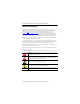
ControlNet Modular Repeater Short-distance Fiber Module Important User Information Solid-state equipment has operational characteristics differing from those of electromechanical equipment. Safety Guidelines for the Application, Installation and Maintenance of Solid State Controls (Publication SGI-1.1 available from your local Rockwell Automation sales office or online at http://www.rockwellautomation.
ControlNet Modular Repeater Short-distance Fiber Module 3 Environment and Enclosure ATTENTION: This equipment is intended for use in a Pollution Degree 2 industrial environment, in overvoltage Category II applications (as defined in IEC publication 60664-1), at altitudes up to 2000 m (6562 ft) without derating. This equipment is considered Group 1, Class A industrial equipment according to IEC/CISPR Publication 11.
ControlNet Modular Repeater Short-distance Fiber Module North American Hazardous Location Approval The following information applies when operating this equipment in hazardous locations. Informations sur l’utilisation de cet équipement en environnements dangereux. Products marked "CL I, DIV 2, GP A, B, C, D" are suitable for use in Class I Division 2 Groups A, B, C, D, Hazardous Locations and nonhazardous locations only.
ControlNet Modular Repeater Short-distance Fiber Module 5 European Hazardous Location Approval European Zone 2 Certification (The following applies when the product bears the Ex Marking.
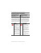
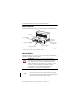
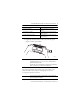
ControlNet Modular Repeater Short-distance Fiber Module Module Components The illustration shows the components that comprise the 1786-RPFS module. Indicators Protective Caps Right-side Backplane Connector with Protective Cap Channel 1 Fiber Port Module Locking Tab Channel 2 Fiber Port . Both sides of the module contain a backplane connector. 30073 Mount the Module Mount the module on a 35 x 7.5 mm (1.38 x 0.30 in.) DIN rail, Allen-Bradley part number 199-DR1, 46277, EN 50022.
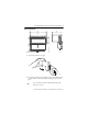
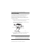
ControlNet Modular Repeater Short-distance Fiber Module 7 Mounting Dimensions 111 (4.44) 100 (4.0) 69 (2.76) 96.8 (3.87) 90 (3.6) All dimensions are in mm (in.). 30082 1. Position the module at a 30° angle. 30075 2. Hook the lip on the back of the module to the top of the DIN rail and press the bottom of the module until the locking tab snaps securely in place. TIP Use a screwdriver to move the locking tab downward, if the module is not secured.
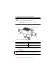
ControlNet Modular Repeater Short-distance Fiber Module WARNING: If you insert or remove the module while backplane power is on, an electrical arc can occur. This could cause an explosion in hazardous location installations. Be sure that power is removed or the area is nonhazardous before proceeding. Protective Backplane Cap DIN Rail Protective Cap Both sides of the module contain a backplane connector. 30078 If Then You will connect another module Remove the protective backplane cap.
ControlNet Modular Repeater Short-distance Fiber Module 9 If Then You will use a channel Remove the protective cap from the channel. You will not use a channel Keep the protective cap on to protect the channel from dust. You place the module in storage Keep the protective cap on to protect the channel from dust. 4. If applicable, slide the module to the left to mate with the repeater adapter or another repeater module.
ControlNet Modular Repeater Short-distance Fiber Module Connect the Fiber Module This module requires a pre-terminated zipcord wiring kit. The kits are offered in a variety of lengths. Consult with your local distributor for attenuation specifications before you purchase your fiber media components. The zipcord uses a duplex cable that contains two separate fibers, one for transmit and one for receive. If you are wiring only one channel, you can use either channel 1 or channel 2. 1.
ControlNet Modular Repeater Short-distance Fiber Module 11 ATTENTION: Under certain conditions, viewing the optical port may expose the eye to hazard. When viewed under some conditions, the optical port may expose the eye beyond the maximum permissible exposure recommendations Troubleshoot the Module Use the channel 1 or 2 status indicators to check module status and troubleshoot the module.
ControlNet Modular Repeater Short-distance Fiber Module Specifications Technical Specifications - 1786-RPFS Attribute Value All supply voltages or voltage ranges Backplane: 5V DC, 300 mA Dissipation 2W Communication rate 5 Mbps Mounting orientation Any mounting orientation Minimum enclosure size (HxWxD), approx 304.8 x 196.8 x 101.6 mm (12 x 7.75 x 4 in.
ControlNet Modular Repeater Short-distance Fiber Module 13 Technical Specifications - 1786-RPFS Attribute Value Enclosure type rating None (open-style) North American temp code T5 IEC temp code T4 (1) This includes all loss associated with the fiber link, including splices, fiber attenuation, bulkhead connectors, and the ST terminations.
ControlNet Modular Repeater Short-distance Fiber Module Environmental Specifications - 1786-RPFS Attribute Value Shock, operating 30 g IEC60068-2-27 (Test Ea, Unpackaged Shock) Shock, nonoperating 50 g IEC60068-2-27 (Test Ea, Unpackaged Shock) Emissions Group 1, Class A CISPR 11 ESD immunity 4 kV contact discharges 8 kV air discharges IEC 61000-4-2 Radiated RF immunity IEC 61000-4-3 10V/m with 1 kHz sine-wave 80% AM from 80…2000 MHz 10V/m with 200 Hz 50% Pulse 100% AM at 900 and 1890 MHz 3V/m
ControlNet Modular Repeater Short-distance Fiber Module 15 Certifications(1) - 1786-RPFS Certification(2) Value CE European Union 2004/108/EC EMC Directive, compliant with: • EN 61326-1; Meas./Control/Lab.
Additional Resources These documents contain additional information concerning related Rockwell Automation products. Resource Description ControlNet Coax Taps Installation Instructions, publication 1786-IN007 Document contains procedures and specifications for the installation of ControlNet coaxial taps. ControlNet Coax Media Planning and Installation Guide, publication CNET-IN002 Document describes the components and topologies for creating a ControlNet coax media system.