Installation Instructions ControlNet Modular Repeater Medium-distance Fiber Module Catalog Number 1786-RPFM Topic Page Important User Information 2 Environment and Enclosure 3 North American Hazardous Location Approval 4 European Hazardous Location Approval 5 Module Components 6 Mount the Module 6 Select Fiber Cable 10 Connect the Fiber Module 11 Troubleshoot the Module 12 Specifications 13 Additional Resources 17 About the Module Use the 1786-RPFM module when you need a medium-dist
ControlNet Modular Repeater Medium-distance Fiber Module Important User Information Solid-state equipment has operational characteristics differing from those of electromechanical equipment. Safety Guidelines for the Application, Installation and Maintenance of Solid State Controls (Publication SGI-1.1 available from your local Rockwell Automation sales office or online at http://www.rockwellautomation.
ControlNet Modular Repeater Medium-distance Fiber Module 3 Environment and Enclosure ATTENTION: This equipment is intended for use in a Pollution Degree 2 industrial environment, in overvoltage Category II applications (as defined in IEC 60664-1), at altitudes up to 2000 m (6562 ft) without derating. This equipment is considered Group 1, Class A industrial equipment according to IEC/CISPR 11.
ControlNet Modular Repeater Medium-distance Fiber Module North American Hazardous Location Approval The following information applies when operating this equipment in hazardous locations. Informations sur l’utilisation de cet équipement en environnements dangereux. Products marked "CL I, DIV 2, GP A, B, C, D" are suitable for use in Class I Division 2 Groups A, B, C, D, Hazardous Locations and nonhazardous locations only.
ControlNet Modular Repeater Medium-distance Fiber Module 5 European Hazardous Location Approval European Zone 2 Certification (The following applies when the product bears the Ex Marking.
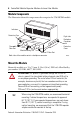
ControlNet Modular Repeater Medium-distance Fiber Module Module Components The illustration shows the components that comprise the 1786-RPFM module. Indicators Protective Caps Channel 1 Fiber Port Right-side Backplane Connector with Protective Cover Module Locking Tab Channel 2 Fiber Port Both sides of the module contain a backplane connector. 42505 Mount the Module Mount the module on a 35 x 7.5 mm (1.38 x 0.30 in.) DIN rail, Allen-Bradley part number 199-DR1, 46277, EN 50022.
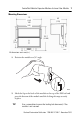
ControlNet Modular Repeater Medium-distance Fiber Module 7 Mounting Dimensions 111 (4.44) 100 (4.0) 69 (2.76) 101.2 (4.048) 90 (3.6) 42501 All dimensions are in mm (in.). 1. Position the module at a 30° angle. 42507 2. Hook the lip on the back of the module to the top of the DIN rail and press the bottom of the module until the locking tab snaps securely in place. TIP Use a screwdriver to move the locking tab downward, if the module is not secured.
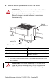
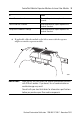
ControlNet Modular Repeater Medium-distance Fiber Module WARNING: If you insert or remove the module while backplane power is on, an electrical arc can occur. This could cause an explosion in hazardous location installations. Be sure that power is removed or the area is nonhazardous before proceeding. Protective Backplane Cap DIN Rail Protective Cap 41900 Both sides of the module contain a backplane connector. If Then You will connect another module Remove the protective backplane cap.
ControlNet Modular Repeater Medium-distance Fiber Module 9 If Then You will use a channel Remove the protective cap from the channel. You will not use a channel Keep the protective cap on to protect the channel from dust. You place the module in storage Keep the protective cap on to protect the channel from dust. 4. If applicable, slide the module to the left to mate with the repeater adapter or another repeater module.
ControlNet Modular Repeater Medium-distance Fiber Module You can attach a maximum of four modules to the repeater adapter, or, the number of modules whose total power consumption does not exceed 1.6 A @ 5V DC, whichever occurs first. IMPORTANT If you exceed the module or power limit, you may damage the repeater adapter and modules. Select Fiber Cable The type of fiber cable you choose depends on the network environment. The quality of fiber cable determines the distance you can achieve.
ControlNet Modular Repeater Medium-distance Fiber Module 11 Connect the Fiber Module If you are wiring only one channel, you can use either channel 1 or channel 2. Do these steps to connect to channel 1, receive (RX). 1. Align the knob of the cable connector with the groove of the module connector. 2. Insert the connector into channel 1 RX. 3. Twist the receive connector until the bayonet lug locks into place. 4. Repeat these procedures to connect to channel 1, transmit (TX).
ControlNet Modular Repeater Medium-distance Fiber Module Troubleshoot the Module Use the channel 1 or 2 status indicators to check module status and troubleshoot the module. Channel 1 Status Channel 2 Status 30041 Indicator Probable Cause Off Repeater not connected to the power supply. Green Channel is operating normally. Flashing Green No activity on the channel. ATTENTION: Class 1 laser product. Laser radiation is present when the system is open and interlocks bypassed.
ControlNet Modular Repeater Medium-distance Fiber Module 13 Specifications Technical Specifications - 1786-RPFM Attribute Value All supply voltages or voltage ranges Backplane: 5V DC, 400 mA Dissipation 2W Communication rate 5 Mbps Mounting orientation Any mounting orientation Minimum enclosure size (HxWxD), approx 304.8 x 196.8 x 101.6 mm (12 x 7.75 x 4 in.) Fiber type 62.5/125 Micron multimode OM-1 fiber Power level TX power, min (-16 dBm) @ 25 °C (77 °F) into 62.
ControlNet Modular Repeater Medium-distance Fiber Module Environmental Specifications - 1786-RPFM Attribute Value Temperature, operating 0…60 °C (32…140 °F) IEC 60068-2-1 (Test Ad, Operating Cold), IEC 60068-2-2 (Test Bd, Operating Dry Heat), IEC 60068-2-14 (Test Nb, Operating Thermal Shock) Temperature, surrounding air, max 60 °C (140 °F) Temperature, nonoperating -40…85 °C (-40…185 °F) IEC 60068-2-1 (Test Ab, Unpackaged Nonoperating Cold), IEC 60068-2-2 (Test Bb, Unpackaged Nonoperating Dry Hea
ControlNet Modular Repeater Medium-distance Fiber Module 15 Environmental Specifications - 1786-RPFM Attribute Value Emissions Group 1, Class A CISPR 11 ESD immunity 4 kV contact discharges 8 kV air discharges IEC 61000-4-2 Radiated RF immunity IEC 61000-4-3 10V/m with 1 kHz sine-wave 80% AM from 80…2000 MHz 10V/m with 200 Hz 50% Pulse 100% AM at 900 and 1890 MHz 3V/m with 1 kHz sine-wave 80% AM from 2000…2700 MHz Rockwell Automation Publication 1786-IN011C-EN-P - November 2010
ControlNet Modular Repeater Medium-distance Fiber Module Certifications(1) - 1786-RPFM Certification(2) Value UL UL Listed Industrial Control Equipment. See UL File E65584. CSA CSA Certified Process Control Equipment. See CSA File LR54689C. CSA Certified Process Control Equipment for Class I, Division 2 Group A, B, C, D Hazardous Locations. See CSA File LR69960C.
ControlNet Modular Repeater Medium-distance Fiber Module 17 Additional Resources These documents contain additional information concerning related Rockwell Automation products. Resource Description ControlNet Coax Taps Installation Instructions, publication 1786-IN007 Document contains procedures and specifications for the installation of ControlNet coaxial taps.
ControlNet Modular Repeater Medium-distance Fiber Module Notes: Rockwell Automation Publication 1786-IN011C-EN-P - November 2010
ControlNet Modular Repeater Medium-distance Fiber Module 19 Notes: Rockwell Automation Publication 1786-IN011C-EN-P - November 2010
Rockwell Automation Support Rockwell Automation provides technical information on the Web to assist you in using its products. At http://www.rockwellautomation.com/support/, you can find technical manuals, a knowledge base of FAQs, technical and application notes, sample code and links to software service packs, and a MySupport feature that you can customize to make the best use of these tools.