Installation Instructions ControlNet Dual Copper Repeater Module Catalog Number 1786-RPCD This document describes how to install and apply the 1786-RPCD dual copper repeater module.
ControlNet Dual Copper Repeater Module Important User Information Solid state equipment has operational characteristics differing from those of electromechanical equipment. Safety Guidelines for the Application, Installation and Maintenance of Solid State Controls (Publication SGI-1.1 available from your local Rockwell Automation sales office or online at http://www.ab.com/manuals/gi) describes some important differences between solid state equipment and hard-wired electromechanical devices.
ControlNet Dual Copper Repeater Module ATTENTION 3 Environment and Enclosure This equipment is intended for use in a Pollution Degree 2 industrial environment, in overvoltage Category II applications (as defined in IEC publication 60664-1), at altitudes up to 2000 meters without derating. This equipment is considered Group 1, Class A industrial equipment according to IEC/CISPR Publication 11.
ControlNet Dual Copper Repeater Module ATTENTION Preventing Electrostatic Discharge This equipment is sensitive to electrostatic discharge, which can cause internal damage and affect normal operation. Follow these guidelines when you handle this equipment: • • • • • • ATTENTION Touch a grounded object to discharge potential static. Wear an approved grounding wriststrap. Do not touch connectors or pins on component boards. Do not touch circuit components inside the equipment.
ControlNet Dual Copper Repeater Module IMPORTANT 5 This equipment is not resistant to sunlight or other sources of UV radiation. The secondary of a current transformer shall not be open-circuited when applied in Class I, Zone 2 environments. Equipment of lesser Enclosure Type Rating must be installed in an enclosure providing at least IP54 protection when applied in Class I, Zone 2 environments. This equipment shall be used within its specified ratings defined by Allen-Bradley.
ControlNet Dual Copper Repeater Module North American Hazardous Location Approval The following information applies when operating this equipment in hazardous locations: Informations sur l’utilisation de cet équipement en environnements dangereux: Products marked “CL I, DIV 2, GP A, B, C, D” are suitable for use in Class I Division 2 Groups A, B, C, D, Hazardous Locations and nonhazardous locations only.
ControlNet Dual Copper Repeater Module WARNING WARNING 7 If you insert or remove the module while backplane power is on, an electrical arc can occur. This could cause an explosion in hazardous location installations.If you insert or remove the module while backplane power is on, an electrical arc can occur. This could cause an explosion in hazardous location installations. Be sure that power is removed or the area is nonhazardous before proceeding.
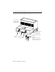
ControlNet Dual Copper Repeater Module The figure below identifies the components of the module: The left side of the module (not shown here) also contains a backplane connector. Indicators Right-side backplane connector with protective cover Channel 1 coax port Module Channel 2 locking tab coax port Publication 1786-IN001B-EN-P - May 2004 75 Ω BNC Trunk line terminators (1786-XT) Important:You must terminate unused channels to maintain the 42210 integrity of your network.
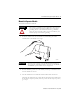
ControlNet Dual Copper Repeater Module 9 Mount the Repeater Module To mount the module on the DIN rail: ATTENTION This product is grounded through the DIN rail to chassis ground. Use zinc plated yellow-chromate steel DIN rail to assure proper grounding. The use of other DIN rail materials (e.g., aluminum, plastic, etc.) that can corrode, oxidize, or are poor conductors, can result in improper or intermittent grounding. 1. Position the module on the 35×7.
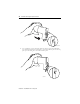
ControlNet Dual Copper Repeater Module 30076-M 4. Use a screwdriver to move the locking tab down while you press the module flush onto the DIN rail. Release the locking tab to secure the module in place. If necessary, push up on the locking tab to secure the module in place.
ControlNet Dual Copper Repeater Module 11 5. Once you attach the modules to the DIN rail, slide the modules to the left to attach to the repeater adapter or another repeater module. You must use a DIN rail end anchor on the right side of the copper module if it is the right-most module. 31493-M IMPORTANT Because the 1786-RPCD repeater module is part of the modular family of ControlNet repeaters, you must use the 1786-RPA repeater adapter to supply power and coordinate the modules’ TX and RX function.
ControlNet Dual Copper Repeater Module 8. Connect the module wiring as shown in Connect the Module For Coax Channels 1 and 2 on page 14. 9. Ground your DIN rail in accordance with local codes using a minimum #14 AWG wire. See page 12 for DIN rail ground wire example. Use Trunk Line Terminators When you are not connecting a trunk line to a channel on the 1786-RPCD repeater module, connect a 75 Ω terminating resistor (1786-XT) to maintain the integrity of your network.
ControlNet Dual Copper Repeater Module 13 Remove the Repeater Module from the DIN Rail To remove the module from the DIN rail, do the following: 1. Insert a screwdriver into the module locking tab. 31491-M 2. Gently pry up on the locking tab. The module should detach from the DIN rail. If the module does not unlock, try more pressure while you pry up on the locking tab with the screwdriver.
ControlNet Dual Copper Repeater Module Connect the Module For Coax Channels 1 and 2 1. Connect the ControlNet tap to port #1. a. Align the knob of the BNC cable connector with the locks of the BNC module connector, and insert the connector into channel 1. Tap BNC connector 75 Ω terminator 31492-M b. Twist the BNC connector until the bayonet lug is locked into place. 2. To connect channel 2, repeat Step 1 for channel 2.
ControlNet Dual Copper Repeater Module 15 Understand Common Topologies The following topologies show how you can use the module. Series Topology The following figure shows the 1786-RPCD wired in series. This topology can be used to extend the trunk line. Connect 1786-RPA repeater adapter to a 24V dc Class 2 power supply.
ControlNet Dual Copper Repeater Module Star Topology The following figure shows a star configuration that supports 16 usable segments. The two 1786-RPA repeater adapters create a central hub with the 1786-RPCD modules forming 16 segments. 16 segments, 2 1786-RPA repeater adapters in series with a maximum of 4 1786-RPCD modules per repeater adapter.
ControlNet Dual Copper Repeater Module 17 Redundant Topology Use redundant media when you need module and media redundancy. With redundant media, the channel-to-channel skew travel time difference must be less than 1.6µ s. Redundant media can be used with series and star topologies. You cannot use redundant media with ring redundant topology. TIP For more information on redundant topology, refer to the ControlNet Fiber Media Planning and Installation Guide, publication CNET-IN001.
ControlNet Dual Copper Repeater Module segment length m Figure 1 Maximum segment length (assumes you are using 1786-RG6 coax cable) 1000 (3280) 750 (2460) 500 (1640) 250 (820) 2 16 32 48 number of taps maximum allowable segment length = 1000m (3280ft) - 16.3m (53.4ft) X [number of taps - 2] 30014-M EXAMPLE If your segment requires 10 taps, the maximum segment length is: 1000m (3280ft) - 16.3m (53.4ft) x [10 - 2] 1000m (3280ft) - 130.4m (427.7ft) = 869.6m (2852.
ControlNet Dual Copper Repeater Module 19 Status Indicators The figure below identifies indicators on the module: Channel 1 status Channel 2 status 31489-M The table below defines Channel 1 and Channel 2 status indicators.
ControlNet Dual Copper Repeater Module Mounting Dimensions The figure below shows the dimensions for mounting the module. 4.44in (111mm) 4.0in (100mm) 3.6in (90mm) 2.76in (69mm) 4.048in (101.
ControlNet Dual Copper Repeater Module Specification Value Emissions CISPR 11: Group 1, Class A ESD Immunity IEC 61000-4-2: 4kV contact discharges 8kV air discharges Radiated RF Immunity IEC 61000-4-3: 10V/m with1kHz sine-wave 80% AM from30MHz to 1000MHz 10V/m with 200Hz 50% Pulse 100% AM at 900MHz EFT/B Immunity IEC 61000-4-4: ±2kV at 5kHz on communications ports Surge Transient Immunity IEC 61000-4-5: ±2kV line-earth (CM) on shielded ports Conducted RF Immunity IEC 61000-4-6: 10Vrms with 1kH
ControlNet Dual Copper Repeater Module Specification Value Wiring Category1 1 - on communications ports Certifications (when product is marked) UL Listed Industrial Control Equipment CSA Certified Process Control Equipment CSA Certified Process Control Equipment for Class I, Division 2 Group A,B,C,D Hazardous Locations CE2 - European Union 89/336/EEC EMC Directive, compliant with: EN 50082-2; Industrial Immunity EN 61326; Meas./Control/Lab.
ControlNet Dual Copper Repeater Module 23 Notes: Publication 1786-IN001B-EN-P - May 2004
Rockwell Automation Support Rockwell Automation provides technical information on the web to assist you in using our products. At http://support.rockwellautomation.com, you can find technical manuals, a knowledge base of FAQs, technical and application notes, sample code and links to software service packs, and a MySupport feature that you can customize to make the best use of these tools.