Installation Instructions ControlNet Modular Repeater Adapter Catalog Number 1786-RPA/B Topic Page Important User Information 2 Environment and Enclosure 3 North American Hazardous Location Approval 4 European Hazardous Location Approval 5 Features and Components of the ControlNet Repeater Adapter 6 Mount the Repeater Adapter Module 8 Wire the Repeater Adapter Module 13 Status Indicators 16 Specifications 19 Additional Resources 23 About the Repeater Adapter Module The 1786-RPA/B Cont
ControlNet Modular Repeater Adapter Important User Information Solid-state equipment has operational characteristics differing from those of electromechanical equipment. Safety Guidelines for the Application, Installation and Maintenance of Solid State Controls (Publication SGI-1.1 available from your local Rockwell Automation sales office or online at http://www.rockwellautomation.
ControlNet Modular Repeater Adapter 3 Environment and Enclosure ATTENTION: This equipment is intended for use in a Pollution Degree 2 industrial environment, in overvoltage Category II applications (as defined in IEC 60664-1), at altitudes up to 2000 m (6562 ft) without derating. This equipment is considered Group 1, Class A industrial equipment according to IEC/CISPR 11.
ControlNet Modular Repeater Adapter North American Hazardous Location Approval The following information applies when operating this equipment in hazardous locations. Informations sur l’utilisation de cet équipement en environnements dangereux. Products marked "CL I, DIV 2, GP A, B, C, D" are suitable for use in Class I Division 2 Groups A, B, C, D, Hazardous Locations and nonhazardous locations only.
ControlNet Modular Repeater Adapter 5 European Hazardous Location Approval European Zone 2 Certification (The following applies when the product bears the Ex Marking.
ControlNet Modular Repeater Adapter Prevent Electrostatic Discharge ATTENTION: This equipment is sensitive to electrostatic discharge, which can cause internal damage and affect normal operation. Follow these guidelines when you handle this equipment: • Touch a grounded object to discharge potential static. • Wear an approved grounding wriststrap. • Do not touch connectors or pins on component boards. • Do not touch circuit components inside the equipment. • Use a static-safe workstation, if available.
ControlNet Modular Repeater Adapter 7 The repeater adapter also provides the following: • Digital re-timing of ControlNet network data • Power to repeater modules • One coax channel • Status indicators The repeater adapter ships with the following items: • One removable terminal block (power connector) attached to the repeater adapter. • One 75 Ω terminator for terminating an unused port. • Two DIN rail locks The illustration shows the components that comprise the 1786-RPA/B repeater adapter module.
ControlNet Modular Repeater Adapter Mount the Repeater Adapter Module This section explains how to mount the 1786-RPA/B repeater adapter module. TIP Horizontal mounting is preferred. Vertical mounting is allowed. We recommend that the 1786-RPA/B module be mounted at the top if vertical mounting is chosen. ATTENTION: This product is grounded through the DIN rail to chassis ground. Use zinc plated yellow-chromate steel DIN rail to assure proper grounding.
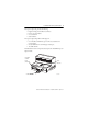
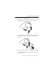
ControlNet Modular Repeater Adapter 9 Do these steps to mount the 1786-RPA/B module. 1. Position the repeater adapter module on the 35 x 7.5 mm (1.4 x 0.3 in.) DIN rail (Allen-Bradley part number 199-DR1) at a 30o angle. 31454A-M 2. Hook the lip on the rear of the 1786-RPA/B repeater adapter module onto the top of the DIN rail, and rotate the repeater adapter module onto the rail. 31454B-M 3. Press the repeater adapter module down onto the DIN rail until flush.
ControlNet Modular Repeater Adapter If the repeater adapter module does not snap into position, use a screwdriver or similar device to move the locking tab down while pressing the repeater adapter flush onto the DIN rail. 31454C-M 4. Release the locking tab to lock the adapter in place. If necessary, push up on the locking tab to lock. 5. Once the repeater adapter module is attached to the DIN rail, slide the repeater modules to the left to mate with the repeater adapter module.
ControlNet Modular Repeater Adapter 11 WARNING: Removal and insertion under power (RIUP) is not supported. This module must be powered down while connecting and disconnecting it from any interconnected modules. If you insert or remove the module while backplane power is on, an electrical arc can occur. This could cause an explosion in hazardous location installations. Be sure that power is removed or the area is nonhazardous before proceeding. 6.
ControlNet Modular Repeater Adapter 7. Repeat steps 1 through 6 for each of the two DIN rail locks. IMPORTANT For proper operation when using a 1786-RPFRXL/B module with a 1786-RPCD module attached to the same 1786-RPA/B repeater module, you must install any 1786-RPCD module to the left side of any 1786-RPFRL or 1786-RPFRXL/B repeater module. 8. Tighten the two screws on the DIN rail lock to a torque of 1.1 N•m (9…11 in•lb). a. Position the DIN rail lock to the DIN rail. b.
ControlNet Modular Repeater Adapter 13 Wire the Repeater Adapter Module This section describes how to wire your module. WARNING: An electrical arc can occur under these circumstances: - when you connect or disconnect the removable terminal block (RTB) with field side power applied - if you connect or disconnect the communications cable with power applied to this module or any device on the network This could cause an explosion in hazardous location installations.
ControlNet Modular Repeater Adapter Vin + and Vin terminals 31456-M Tighten the screws to 0.6…0.8 N•m (5…7 in•lb). 3. Attach the V in - wire to one of the V in - terminals on the RTB. Tighten the screws to 0.6…0.8 N•m (5…7 in•lb). TIP The unused Vin + and Vin - terminals can be used to supply power to other devices. 4. Install the RTB onto the repeater adapter module. Tighten the screws to 0.6…0.8 N•m (5…7 in•lb).
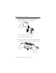
ControlNet Modular Repeater Adapter 15 5. Connect the repeater adapter module to the ControlNet network by connecting the drop line of the coax tap to the BNC connector. BNC Connector 31459-M 6. Terminate any unused coax ports by connecting a 75 Ω terminator to the unused BNC connector. One 75 Ω terminator is shipped with the repeater adapter module.
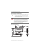
ControlNet Modular Repeater Adapter Status Indicators The status indicators on the repeater adapter module can be interpreted alone or together. Repeater Modules Repeater Adapter + + 24V COM REPEAT MODU LESER COM REPEAT ADAP TERER 31453-M The following three tables list different combinations of status indicators and their interpretations.
ControlNet Modular Repeater Adapter 17 Table 1 -Power-up and Fault Conditions Indicator Description Action Alternating red/green Repeater adapter module is being powered-up or reset. Do nothing. The repeater adapter module is operating properly. Solid red A jabber condition has occurred. Another node or repeater on the network is transmitting constantly. Check the network and components for proper operation. Off Repeater adapter module is not powered up or has failed.
ControlNet Modular Repeater Adapter Table 3 -Repeater Modules Status Indicator Indicator Description Action Solid green Error-free data is being recovered at all of the attached repeater modules. Do nothing. This is the normal operating mode. Flashing green/off Data with errors is occasionally being recovered at some or all of the repeater modules. • This situation will normally correct itself. If the situation persists, check the following: • All BNC connector pins are seated properly.
ControlNet Modular Repeater Adapter 19 Specifications Technical Specifications - 1786-RPA/B Attribute 1786-RPA/B Power consumption, max 16.8 W Power dissipation, max 8.8 W Input voltage rating, max 700 mA @ 24V DC, Class 2/SELV(1) Input voltage range 18…36V DC Backplane output current, max 1.6A @ 5V DC Minimum enclosure size (HxWxD), approx 304.8 x 196.8 x 101.6 mm (12 x 7.75 x 4 in.
ControlNet Modular Repeater Adapter Environmental Specifications - 1786-RPA/B Attribute 1786-RPA/B Temperature, operating 0…60 °C (32…140 °F) IEC 60068-2-1 (Test Ad, Operating Cold), IEC 60068-2-2 (Test Bd, Operating Dry Heat), IEC 60068-2-14 (Test Nb, Operating Thermal Shock) Temperature, surrounding air, max 60 °C (140 °F) Temperature, nonoperating -40…85 °C (-40…185 °F) IEC 60068-2-1 (Test Ab, Unpackaged Nonoperating Cold), IEC 60068-2-2 (Test Bb, Unpackaged Nonoperating Dry Heat), IEC 60068-2
ControlNet Modular Repeater Adapter 21 Environmental Specifications - 1786-RPA/B Attribute 1786-RPA/B Radiated RF immunity 10V/m with 1 kHz sine-wave 80% AM from 80…2000 MHz 10V/m with 200 Hz 50% Pulse 100% AM at 900 and 1890 MHz 1V/m with 1 kHz sine-wave 80% AM from 2000…2700 MHz IEC 61000-4-3 EFT/B immunity ±4 kV at 5 kHz on power ports ±4 kV at 5 kHz on communication ports IEC 61000-4-4 Surge transient immunity ±1 kV line-line (DM) and ±2 kV line-earth (CM) on power ports ±2 kV line-earth (CM) on
ControlNet Modular Repeater Adapter Certifications(1) - 1786-RPA/B Certification(2) 1786-RPA/B CE European Union 2004/108/EC EMC Directive, compliant with the following: • EN 61326-1; Meas./Control/Lab.
ControlNet Modular Repeater Adapter 23 Additional Resources These documents contain additional information concerning related Rockwell Automation products. Resource Description ControlNet Coax Taps Installation Instructions, publication 1786-IN007 Document contains procedures and specifications for the installation of ControlNet coaxial taps.
Rockwell Automation Support Rockwell Automation provides technical information on the Web to assist you in using its products. At http://www.rockwellautomation.com/support/, you can find technical manuals, a knowledge base of FAQs, technical and application notes, sample code and links to software service packs, and a MySupport feature that you can customize to make the best use of these tools.