
User Manual

Publication 1785-5.19 - January 1999 PN 955134-73
Copyright 1999 of Rockwell International Corporation. Printed in the U.S.A.
Connection capabilities
Transceiver interface
Fiber optic interface
plugged directly on to the AUI interface of connected device
or connected by an AUI cable (50 m max. length)
Fiber optic cable segment maximum
2000 m (50/125 microns) or 3000 m (62.5/125 microns) long
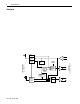
Connections with pin assignments
Transceiver interface
(15-pin sub-D plug)
Fiber optic interface
Input:DO-A: pin 3; DO-B: pin 10
Output:DI-A: pin 5; DI-B: pin 12
Collision detect:CI-A: pin 2; CI-B: pin 9
Power:GND: pin 6; +12 V: pin 13
Shielding:pin 1, 4, 8, 11, 14
2 x IEC 874-10 BFOC/2.5 sockets
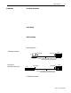
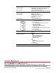
Displays
* green LED: LINK (link status)
on - fiber optic connection OK
* yellow LED: RX (Rx data)
on - data being received over fiber optic cable link
* red LED: CD (collision detect)
brief flash – data collision
continuously on – jabber control active
* yellow LED: TX (Tx data)
on - data being transmitted through fiber optic cable link
* green LED: P (power)
on – supply voltage present
Conductors/Wire Size/Category
Category 1
1
Agency Certification
(when product is marked)
• Information Technology Equipment
• Industrial Control Equipment
• Class I, Div. 2, Groups A, B. C, D
Hazardous Location
• EN 50082-1, 2
• EN 55022, Radiated Emission Class B
• EN 60950
FCC Part 15, SubPart B
1
Refer to the Industrial Automation Wiring and Grounding Guidelines for Noise Immunity, publication 1770-4.1.
LINK
RX
CD
TX
P
CUS