
Installation Instructions Instruction Manual

1785-5.18 - January 1999
Coax Transceiver for 10BASE2 7
Technical Data
Operating voltage +12 V
Current consumption (no signal) 2 50 mA
Bit rate (Manchester Code) 10 Mbit/s
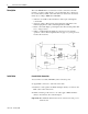
Coaxial cable interface: Transmitter
AC
DC
Rise/fall time
Harmonic components:
1st harmonic
2nd harmonic
3rd harmonic
4th harmonic
5th harmonic
6th harmonic
7th harmonic and higher
1.9 V +0.35 V, –0.5 V
–1.025 V ±0.1 V
25 ns ±20%
–34 dB
–23 dB
–40 dB
–39 dB
–40 dB
–47 dB
–55 dB
Preamble loss transmit ≤ 2 bit
Stady State Delay 15 ns
Jabber protect time out 25 ms
Jabber reset 500 ms
Coaxial cable interface: Receiver
Coaxial cable Input current 5 µA
Capacitive load 2 pF
Input resistance > 100 kΩ
Noise suppression –250 mV
Preamble loss receive 1 bit (max. 3 bit)
Steady State Delay 10 ns
Collision Detect threshold –1.6 V
Transceiver interface (AUI)
Input:
Terminating resistance
Sensitivity
Maximum DC component
78 Ω ±1%
500 mVPP
± 50 V
Output:
Output voltage
(data and CD signal)
CD signal frequency
SQE Test (heart beat)
delay time
length
AUI cable length
1.6 VPP
10 MHz ± 10%
can be disabled
1100 ns
1000 ns
0 to 50 m max.
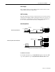
Connections with pin assignments
Transceiver interface
(15-pin sub-D plug)
Coaxial cable interface
Input: DO-A: Pin 3; DO-B: Pin 10
Output: DI-A: Pin 5; DI-B: Pin 12
Collision detect:CI-A: Pin 2; CI-B: Pin 9
Power: GND: Pin 6; +12 V: Pin 13
Shielding: Pin 1, 4, 8, 11, 14
1 BNC socket