
User manual

Operating Your PLC-5 Backup System
Chapter 5
5-11
T
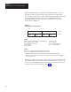
able 5.C
Extended
Status Bits (W1)
Bit
1
Description
10 1785-BCM series A module; when on, this bit indicates that the other 1785-BCM module is
series A.
11 Fast Data Transfer mode; when on, this bit indicates that the data valid bit is set to 1 (one)
as soon as the secondary module receives a data block. When off, this bit indicates that the
data valid bit is 1 (one) only when the secondary module receives the complete data
segment.
12 Reserved – always 0
13 Reserved – always 0
14 Reserved – always 0
15 Reserved – always 0
16 Switchover Diagnostic; this bit is always off, but if during a switchover condition this bit is
on, it means that the module must be replaced.
17 1785-BEM module; this bit is on when there is a 1785-BEM backup expansion module in
the system.
1
Bits 0 through 7 (least significant byte of W1) are unused and reserved. For W1, bit 0 is the
least-significant bit and bit 17 is the most-significant bit.
The second auxiliary status word address corresponds to the right-most slot of
the first I/O module group in the I/O chassis. This word shows the channel
configurations of the 1785-BCM and 1785-BEM (if any) modules and also
indicates an error condition in any of these channels.
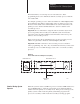
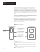
The most-significant byte of this word corresponds to Channels 1A and 1B of
the 1785-BCM module. The least-significant byte corresponds to Channels 2A
and 2B of the 1785-BEM module. Refer to Figure 5.7.
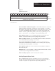
Figure 5.7
Second
Auxiliary Diagnostics/Status W
ord
00
07 10 03 04 13 14 17
W2
Channel 1A
Channel 1B Channel 2A Channel 2B
Error
Bit
11059I
= error bit per channel