
User manual
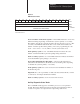

Bits
Word
2
W
ord 1
. . . W
ord 64
W
ord 3
11057I
Operating Your PLC-5 Backup System
Chapter 5
5-9
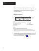
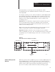
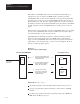
Figure 5.5
BTW Instruction W
ords
15 14 13 12 11 10 09 08 07 06 05 04 03 03 01 00
NUMBER OF BLOCKS IN SEGMENT
BLOCK IDENTIFICA
TION
1
62 WORDS OF DA
TA
(PRIMAR
Y PROCESSOR ONL
Y)
1
Reserved for future use
Word 1: Number of Blocks in Segment — In the BTW instruction, word 1 has
different meanings depending on whether the system is primary or secondary.
The number of blocks in a segment should be the same in both processors. (The
secondary 1785-BCM module checks this word to make sure it matches the
number of blocks specified in the primary.) If not, the programming error bit
(local — bit 3, remote — bit 11) will be on in the system status word.
In the primary system, word 1 of the BTW instruction indicates the total
number of blocks that make up the data package being transferred.
In the secondary system, word 1 of the BTW instruction indicates the number
of blocks that make up the package to be received.
Word 2: Block Identification (Block ID) — Word 2 of this instruction is
called the block identification (block ID) word. Its meaning varies depending
on whether the system is primary or secondary.
In the primary system, the word is reserved for the identification number of
the block being sent.
Important: It is your responsibility to make sure that each data block you want
to send has its own unique identification number.
In the secondary system, word 2 is not used and is reserved.
Auxiliary Diagnostics/Status Words
The 1785-BCM module appears to the PLC-5 processor as a 32-point I/O
module. This means that the I/O chassis physical slot in which the module is
located corresponds to two input and two output image table words.